Multi-roller square paper cup knurling mechanism

A knurling and square technology, applied in papermaking, paper/cardboard containers, container manufacturing machinery, etc., can solve the problems of slow production speed, precision discount, short service life, etc., to improve knurling production speed and ensure knurling quality , the effect of fewer moving parts

Pending Publication Date: 2019-12-20
ZHEJIANG RUIDA MACHINERY
View PDF1 Cites 2 Cited by
  • Summary
  • Abstract
  • Description
  • Claims
  • Application Information

AI Technical Summary

Problems solved by technology

For paper cups and paper bowls with a square shape (the square here does not refer to a specific quadrilateral, it can be a hexagon or other polygons), it is difficult to realize knurling at the bottom of the cup, so the existing technology generally adopts expansion and compression molding, but there are also extreme If the knurling method is seldom used, see the patent No. 200610151940.9 and the patent name "Knurling Device for Square Paper Cup Bottom of Paper Cup Forming Machine"
The technical solution adopted in this patent is to push the radial movement of the slider through the up and down movement of the ejector rod. The knurl wheel is installed on the slider. The disadvantage is that the ejector rod needs to move up and down, and the up and down movement of the ejector rod is driven by the cam. The cam is far away from the knurling part, and the accuracy of the cam curve is greatly reduced when it is transmitted to the knurling wheel. It is difficult to maintain the same contact pressure between the kn

Method used


Image

  • Multi-roller square paper cup knurling mechanism
  • Multi-roller square paper cup knurling mechanism
  • Multi-roller square paper cup knurling mechanism

Examples


Embodiment Construction

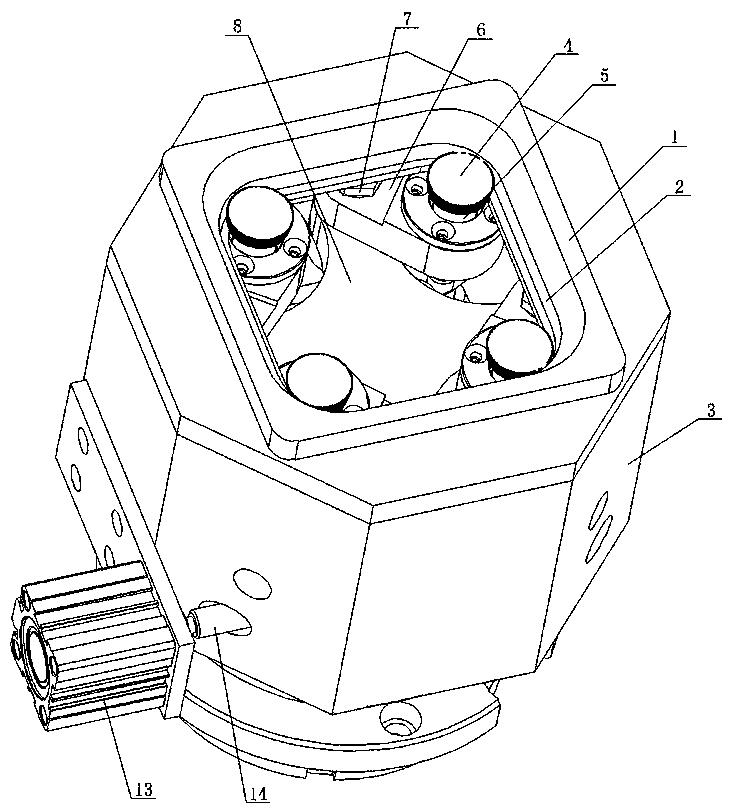
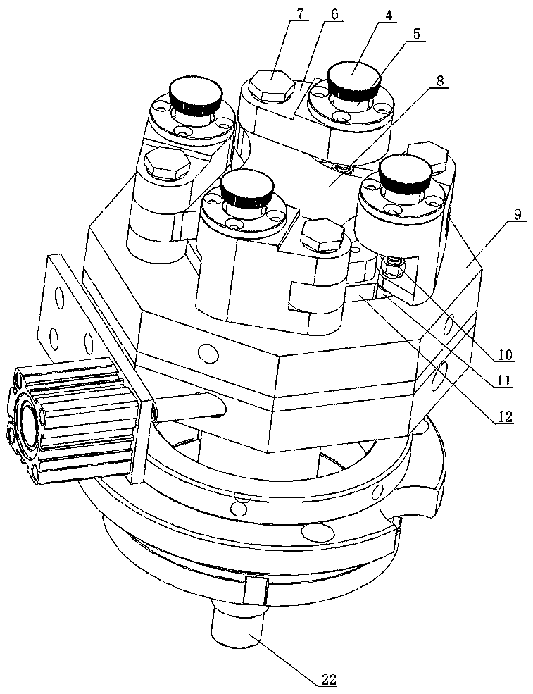
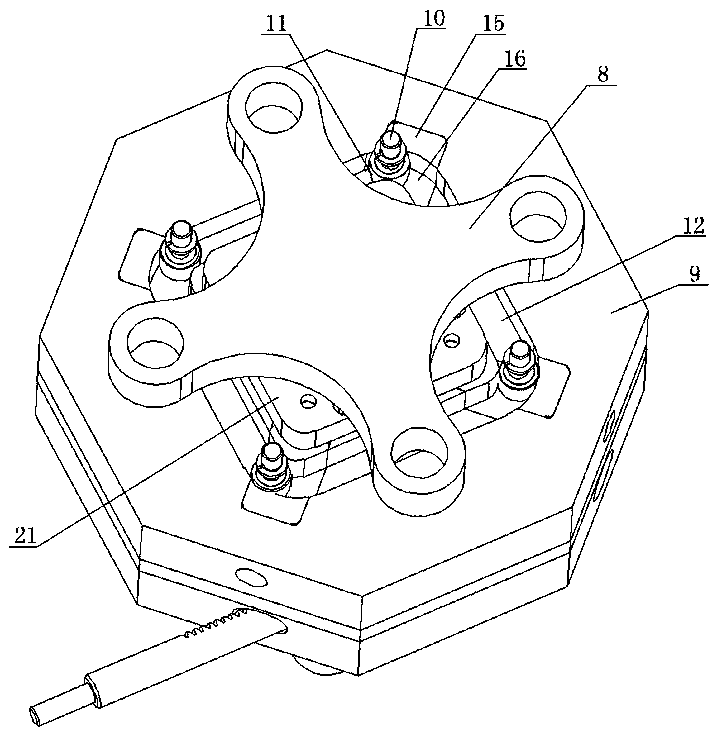
[0018] As shown in the figure, the multi-roller square paper cup knurling mechanism of the present invention includes a knurling sleeve 1 and a knurling wheel 4. The knurling sleeve 1 is fixedly connected to the upper part of the knurling seat 3, and the knurling sleeve 1 has a regular quadrilateral square shape. The inner cavity 2, the knurling wheel 4 is set in the square inner cavity 2, there are four knurling wheels 4, and the four knurling wheels 4 correspond to the four sides of the square inner cavity 2 respectively, and the knurling wheel 4 is connected to the vertical axle 5 On the bottom of the knurling wheel 4, there is a guide roller 11 coaxial with the knurling wheel 4. The guide roller 11 rolls in the cam groove 12, the cam groove 12 is opened on the cam disc 9, and the cam disc 9 is fixed on the In the knurling seat 3, the cam groove 12 is also a regular quadrilateral, and the cam groove 12 keeps the same distance between the knurling wheel 4 and the square inner...


PUM


Abstract

The invention discloses a multi-roller square paper cup knurling mechanism. The multi-roller square paper cup knurling mechanism comprises a knurling sleeve and knurling wheels. The knurling sleeve isfixedly connected to the upper portion of a knurling seat. The knurling sleeve is provided with a square inner cavity. The knurling wheels are arranged in the square inner cavity. The multi-roller square paper cup knurling mechanism is characterized in that the knurling wheels are arranged, the knurling wheels correspond to a plurality of edges of the square inner cavity, the knurling wheels areconnected to vertical wheel shafts, guide rollers which act together along with the knurling wheels are arranged below the knurling wheels, and the guide rollers are arranged in a cam groove in a rolling manner; the cam groove is formed in a cam plate, the cam plate is fixed in the knurling seat, the cam groove is also square, the cam groove enables the knurling wheels to always maintain the samedistance from the square inner cavity wall of the knurling sleeve during knurling, and the guide rollers are pushed by a power driving mechanism along the rolling of the cam groove. The multi-roller square paper cup knurling mechanism is simple in structure and can better realize the action and quality of the square cup knurling, and the speed is increased.

Description

technical field [0001] The invention relates to the technical field of paper cup and bowl production, in particular to a knurling mechanism of a paper cup or paper bowl machine. Background technique [0002] In the production process of paper cups and paper bowls, the knurling operation on the bottom of the paper cups and paper bowls is required, and the knurling operation must be completed by the knurling mechanism at the bottom of the cup. For paper cups and paper bowls with a square shape (the square here does not refer to a specific quadrilateral, it can be a hexagon or other polygons), it is difficult to realize knurling at the bottom of the cup, so the existing technology generally adopts expansion and compression molding, but there are also extreme If the knurling method is seldom used, see the patent No. 200610151940.9 and the patent name "Knurling Device for Square Paper Cup Bottom of Paper Cup Forming Machine". The technical solution adopted in this patent is to p...

Claims


Application Information

Patent Timeline
IPC IPC(8): B31B50/88B31B110/30B31B110/35B31B105/00
CPCB31B50/88B31B2105/00B31B2110/30B31B2110/35
Inventor 胡文斌陈志平
Owner ZHEJIANG RUIDA MACHINERY
Why Eureka
Try Eureka