

Bobbin loader used for industrial sewing machine
A technology for industrial sewing machines and thread reels, which is applied in the field of sewing machine manufacturing, can solve the problems of large wire space occupation, low wire efficiency, loose yarn edges, etc., and achieve the effects of reducing occupied area, improving efficiency, and promoting fixation
- Summary
- Abstract
- Description
- Claims
- Application Information
AI Technical Summary
Problems solved by technology
Method used
Image

Examples
Embodiment Construction
[0029] The present invention will be further described in detail below in conjunction with the embodiments and the accompanying drawings, but the embodiments of the present invention are not limited thereto.
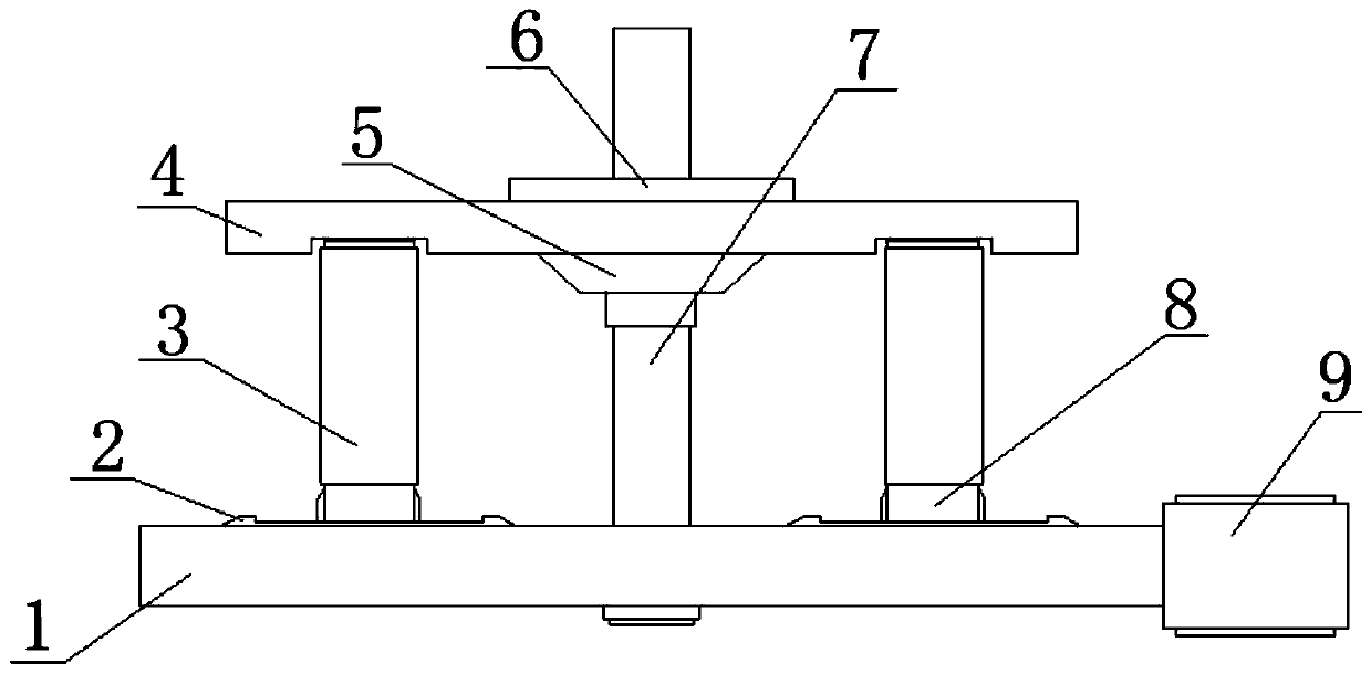
[0030] Such as figure 1 As shown, the thread reel rack for industrial sewing machines in this embodiment includes a bottom plate 1 and a two-dimensional linear module 2 . Bottom plate 1 adopts steel plate to make, and steel plate can be made into groove shape, is used for collecting the debris such as thread end that produces when the wire reel frame works normally. In order to facilitate the movement of the wire rack, a two-dimensional linear module needs to be introduced. The fixed module of the two-dimensional linear module is fixed on the ground, the moving module of the two-dimensional linear module slides vertically relative to the fixed module of the two-dimensional linear module, and the bottom of the base plate 1 is welded on the bottom of the two-dimensional l...
PUM
 Abstract
Description
Claims
Application Information