A cleaning machine with a cleaning guide groove

A technology of cleaning machine and cleaning guide, which is used in the cleaning of open water surfaces, earthmoving machines/shovels, construction, etc., which can solve the problem of fast water flow, failure of cleaning grabs to remove floating objects on the surface, and inability to clean up. Problems such as underwater suspended dirt of the trash rack can reduce the bottom pressure, improve the grabbing efficiency, and reduce the rubbing force.

Active Publication Date: 2022-01-28
SICHUAN ORIENT HYDROELECTRIC ENG
View PDF8 Cites 0 Cited by
  • Summary
  • Abstract
  • Description
  • Claims
  • Application Information

AI Technical Summary

Problems solved by technology

[0004] The purpose of the present invention is to solve the above-mentioned problems existing in the prior art, and to provide a cleaning machine with a cleaning channel. Soon, the dirt cleaning grab could not be inserted into the floating objects on the surface to clean up the floating objects on the surface, and it was unable to slide down the trash rack to a deeper level underwater to clean up the technical problems of underwater suspended dirt stored on the trash rack

Method used


Image

  • A cleaning machine with a cleaning guide groove
  • A cleaning machine with a cleaning guide groove
  • A cleaning machine with a cleaning guide groove

Examples


Embodiment Construction

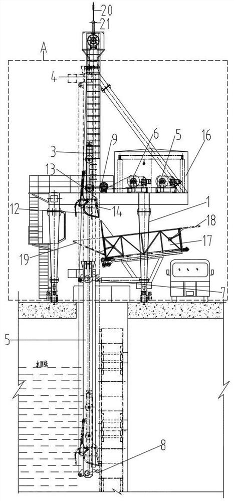
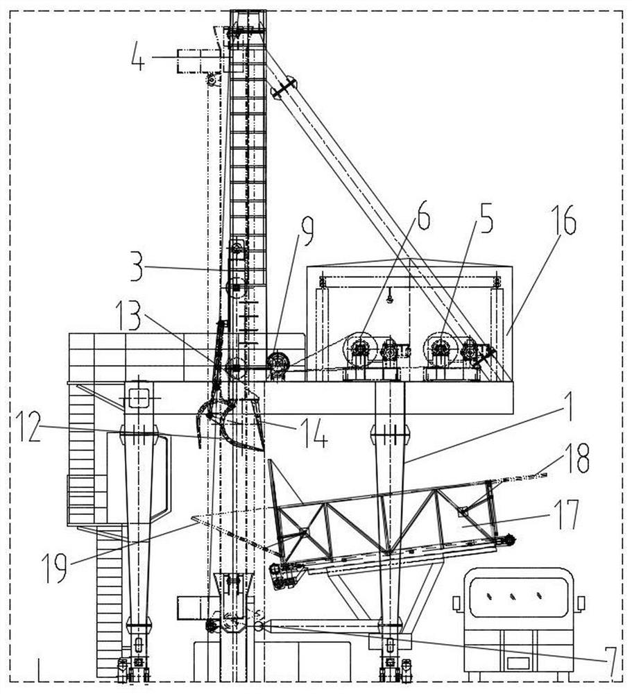
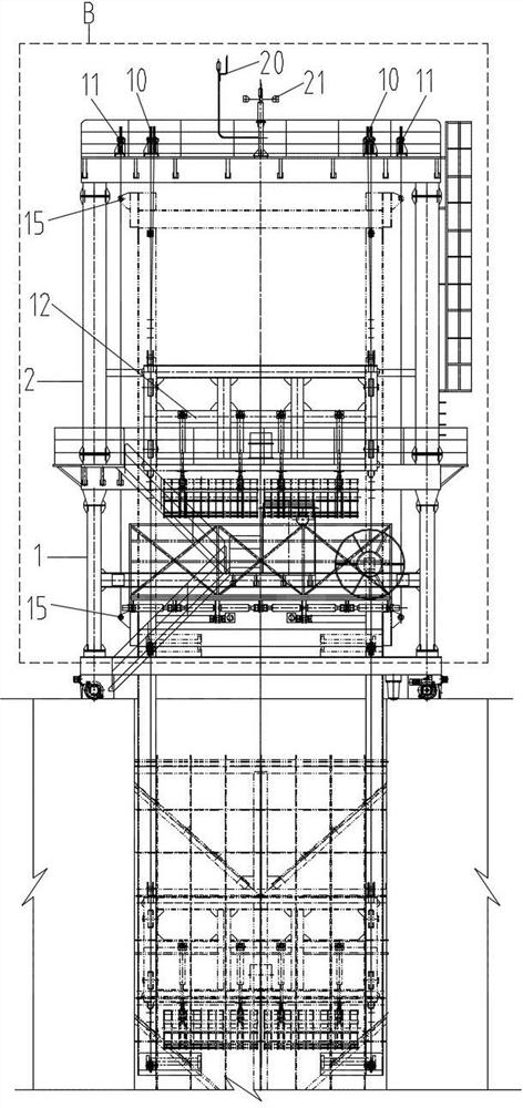
[0030] The invention provides a cleaning machine with a cleaning guide trough, which includes a walking door frame, a dirt grabbing mechanism 3, a cleaning guide trough 4, a guide trough lifting mechanism 5 and a grab bucket lifting mechanism 6. Groove lifting mechanism 5 and grab bucket lifting mechanism 6 are all fixed on the walking gantry, and described cleaning guide groove 4 is a U-shaped channel steel in cross section, and described cleaning guide groove 4 is fixed with guide groove lifting mechanism 5 connected; the dirt grabbing mechanism 3 is fixedly connected with the grab lifting mechanism 6, and the dirt grabbing mechanism 3 is located in the cleaning channel 4; the bottom of the cleaning channel 4 is provided with a lower support wheel 8, The upper support wheel 7 for supporting the decontamination guide groove 4 is fixedly arranged on the walking type gantry, and the decontamination guide groove 4 passes through the upper support wheel 7 and the lower support whe...


PUM


Abstract

The invention discloses a cleaning machine with a cleaning guide trough, which comprises a walking door frame, a dirt grabbing mechanism, a cleaning guide trough, a guide trough lifting mechanism and a grab bucket lifting mechanism, a guide trough lifting mechanism and a grab bucket The lifting mechanism is fixed on the walking gantry, the cleaning guide groove is fixedly connected with the guide groove lifting mechanism; The upper support wheel for supporting the cleaning channel is fixed on the door frame. Under the control of the guide channel lifting mechanism, the cleaning channel enters the water along the surface of the trash rack through the upper support wheel and the lower support wheel, and the grab lifting mechanism It is used to control the lifting and lowering of the dirt grabbing mechanism in the cleaning guide groove. The invention solves the problem that there is no guide groove in front of the trash rack in front of the dam of the hydropower station, and the water flow speed of many riverbed hydropower stations is very fast. The cleaning grab cannot be inserted into the floating objects on the surface for cleaning, and it cannot slide down to the deep underwater along the trash rack. The technical problem of cleaning up the suspended dirt on the trash rack.

Description

technical field [0001] The invention belongs to the technical field of water surface and underwater decontamination, and in particular relates to a decontamination machine with a decontamination guide groove. Background technique [0002] In water conservancy and hydropower projects, especially in hydropower stations, the trash rack is used as the first barrier of the water inlet of the generating set. Its function is mainly to intercept floating dirt in the water and prevent floating objects from flowing into the generating set through the water inlet. If the trash rack floats accumulate too much, once the trash rack is damaged, the float will flow into the generator set through the penstock, which will cause a major accident. [0003] At present, the cleaning machines commonly used in domestic hydropower stations mainly have two working modes. One is that the cleaning bucket of the cleaning machine enters the existing cleaning guide trough before the trash rack. Take the ...

Claims


Application Information

Patent Timeline
Patent Type & Authority Patents(China)
IPC IPC(8): E02F5/28E02B15/10
CPCE02F5/28E02B15/10
Inventor 洪盛荣邓仕路陈启春张惠明
Owner SICHUAN ORIENT HYDROELECTRIC ENG
Why Eureka
Try Eureka