
Vibration-attenuating drive connection device of electromagnetic power-off brake

A technology for electromagnetic loss of power and connection device, applied in the field of machinery, can solve problems affecting user user experience, noise and vibration, etc., and achieve the effect of improving user experience, eliminating noise, and good positioning

Pending Publication Date: 2019-12-20
TAIZHOU HEZI ELECTRIC CO LTD
View PDF0 Cites 1 Cited by
  • Summary
  • Abstract
  • Description
  • Claims
  • Application Information

AI Technical Summary

Problems solved by technology

The iron core of the electromagnetic power-off brake generates a magnetic field after the winding is powered on, and the armature is sucked back. At this time, the armature compresses the spring fixed in the iron core, and the motor shaft connected to the brake disc through the coupling device is in a free rotation; when the iron After the core is de-energized, the magnetic field of the iron core disappears and loses the suction force on the armature. The spring will eject the armature, and the armature and the brake disc will be pressed against each other. The brake disc will generate braking torque on the brake disc through the friction plate to limit the brake disc. The rotation of the brake disc and the rotor is connected by a transmission coupling device, so the rotation of the motor rotor is limited
[0003] The working principle of the electromagnetic power-off brake determines that the brake disc has a degree of freedom of displacement in the axial direction when it is working, which requires a certain gap in the transmission connection between the brake disc and the rotor. The existence of the gap is very likely to cause the motor to run. Noise and vibration are generated at the transmission connection part, which affects the user experience of the user

Method used


Image

  • Vibration-attenuating drive connection device of electromagnetic power-off brake
  • Vibration-attenuating drive connection device of electromagnetic power-off brake
  • Vibration-attenuating drive connection device of electromagnetic power-off brake

Examples


Embodiment 1

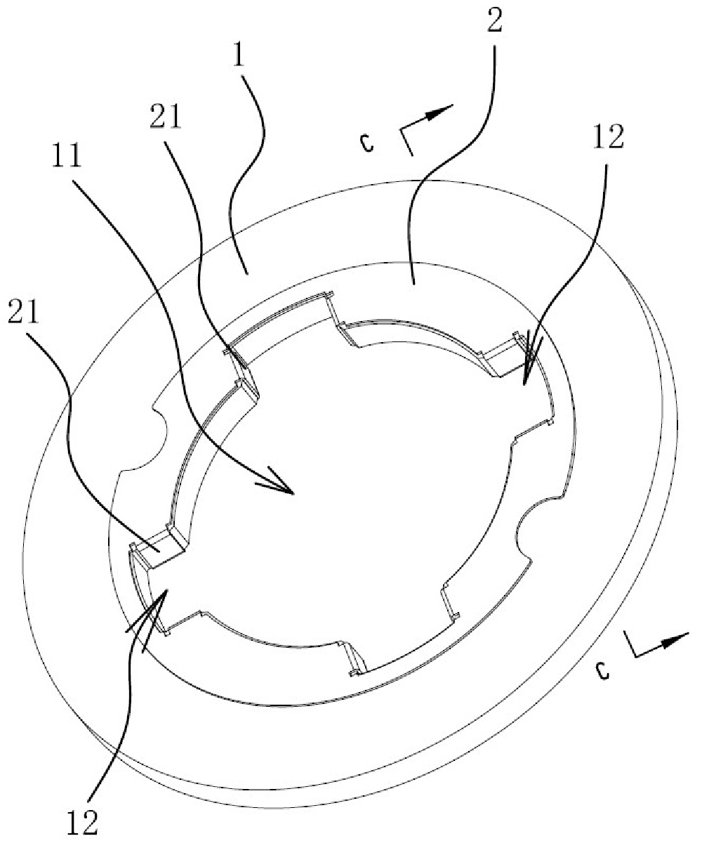
[0032] Such as figure 1 with figure 2 As shown, the vibration-damping transmission coupling device of the electromagnetic power-off brake includes a brake disc 1, the middle part of the brake disc 1 is provided with a connection hole 11, and the hole wall of the connection hole 11 is recessed to form an inner spline groove 12.

[0033] An elastic sheet 2 is arranged on the brake disc 1, and the elastic sheet 2 is made of metal elastic material. The elastic sheet 2 includes an annular elastic sheet substrate 27 that is in contact with the end surface of the brake disc 1, and the elastic sheet substrate 27 is provided with each spline groove 12 corresponding to the center hole of the brake disk to be folded inwards and formed into the spline groove. The baffle 21 next to the two side walls of the spline groove, such as Figure 4 with Figure 5 As shown, when the blocking piece is in a free state, an angle B is formed between the side wall of the spline groove and the angle B...

Embodiment 2

[0037] Embodiment 2: as Figure 6-Figure 10 As shown, when the blocking piece 21 is in a free state, it has a curved surface shape, and the curved surface shape has an arc-shaped cross section, so that an elastic gap 1211 is formed between the blocking piece 21 and the side wall 121 of the spline groove 12 when the blocking piece 21 is in a free state. The curved shape of the baffle can be compressed by the splines of the rotor so as to eliminate the fit gap between the splines of the rotor and the spline grooves of the brake disc. Such as Figure 10As shown, the minimum distance L between two adjacent baffles 21 is smaller than the width of the rotor spline, so that before the spline of the rotor fits with the brake disc, the spline groove of the brake disc is defined by the two baffles The width is less than the width of the rotor splines. All the other structures of this embodiment are the same as Embodiment 1.


PUM


Abstract

The invention belongs to the technical field of machinery and relates to a vibration-attenuating drive connection device of an electromagnetic power-off brake. The electromagnetic power-off brake comprises a brake disc, wherein a connecting hole is formed in the center of the brake disc, and the wall of the connecting hole is sunken to form internal spline grooves. The electromagnetic power-off brake is characterized in that an elastic sheet is arranged on the brake disc and comprises an elastic sheet substrate contacted with the end surface of the brake disc, block pieces which are folded inwards the spline grooves and formed beside the two side walls of the spline grooves are arranged in the positions, corresponding to the center hole of the brake disc, of the elastic sheet substrate, and when each block piece is in a free state, an elastic gap is formed between the block piece and the side wall of the corresponding spline groove. According to the device, noise between the brake discand a rotor can be effectively reduced.

Description

technical field [0001] The invention belongs to the technical field of machinery, and relates to a vibration-damping transmission coupling device of an electromagnetic power-off brake. Background technique [0002] Electromagnetic power-off brake is composed of iron core, spring, armature, friction plate, brake disc, transmission coupling device and other components, and is mainly used for braking of various motors. The iron core of the electromagnetic power-off brake generates a magnetic field after the winding is powered on, and the armature is sucked back. At this time, the armature compresses the spring fixed in the iron core, and the motor shaft connected to the brake disc through the coupling device is in a free rotation; when the iron After the core is de-energized, the magnetic field of the iron core disappears and thus loses the suction force on the armature. The spring will eject the armature, and the armature and the brake disc will be pressed against each other, ...

Claims


Application Information

Patent Timeline
Patent Type & Authority Applications(China)
IPC IPC(8): F16D65/12F16D65/02
CPCF16D65/02F16D65/12
Inventor 杨海燕杨俊林正华彭鑫
Owner TAIZHOU HEZI ELECTRIC CO LTD
Learn More