A flow automatic control valve

A technology for automatic valve and flow control, applied in valve details, valve devices, engine components, etc., can solve the problems of low regulation precision, inability to control water flow, and high difficulty in operation, and achieve high regulation precision, prolong life, and difficulty in operation. low effect

Active Publication Date: 2020-12-01
盐城市圣明斯精密机械有限公司
View PDF6 Cites 0 Cited by
  • Summary
  • Abstract
  • Description
  • Claims
  • Application Information

AI Technical Summary

Problems solved by technology

The highest water level of the water tank needs to be controlled by adjusting the solenoid valve or hydraulic valve, which is difficult to operate and the control accuracy is not high, and the first-level hydraulic valve of the solenoid valve can only control the opening and closing of the valve, and cannot control the flow of water during the valve's working process

Method used


Image

  • A flow automatic control valve
  • A flow automatic control valve
  • A flow automatic control valve

Examples


Embodiment Construction

[0024] The technical solutions in the present invention will be clearly and completely described below in conjunction with the accompanying drawings in the embodiments of the present invention.

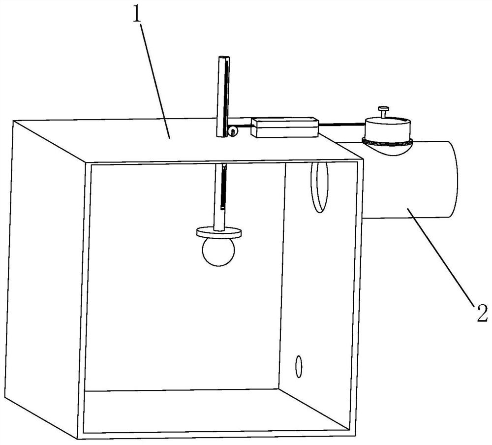
[0025] Such as figure 1 As shown, an automatic flow control valve is fixedly connected with a water tank 1. The water tank 1 is provided with a water outlet and a water inlet, and the valve body 2 is connected to the water inlet.

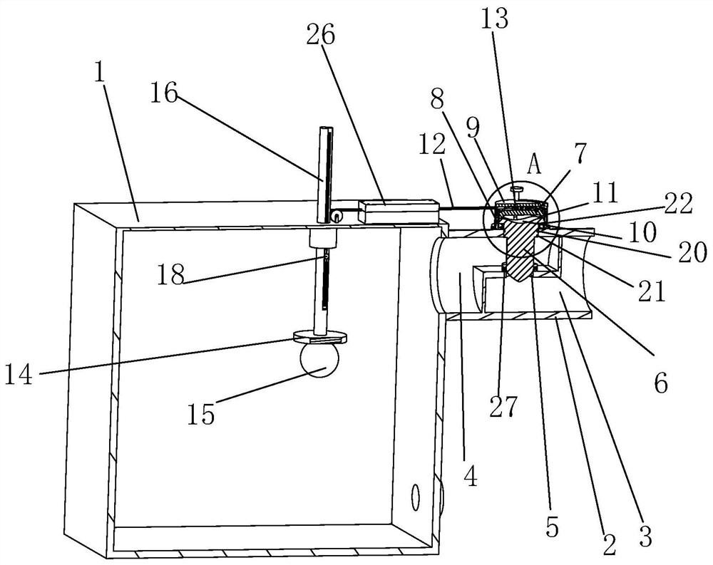
[0026] Such as figure 2 As shown, the valve body 2 is provided with a first space 3 and a second space 4, the first space 3 and the second space 4 communicate through the first through hole 5, water passes through the first through hole 5 from the first space 3, and then flows from the first space 3 to the second space 4. The first pass enters the second space 4, and finally flows into the water tank 1 from the second space 4.

[0027] Such as Figure 4 As shown, the contact surface between the valve core 6 and the valve body 2 is provided with a first ...


PUM


Abstract

The invention discloses an automatic flow control valve which is fixedly connected with a water tank. The automatic flow control valve comprises a valve body, a valve element, a driving assembly and awater level control assembly, wherein the valve body is provided with a first space and a second space which communicate with each other through a first through hole: the valve element is arranged vertical to the first through hole and used for controlling the working state of the first through hole; the driving assembly is used for controlling the working state of the valve element; and the water level control assembly controls the working state of the driving assembly through the water level. According to the automatic flow control valve, the working states of the valve element and the first through hole are controlled by matching the driving assembly with the water level control assembly, thereby reducing the operation difficulty and realizing high regulation and control precision; thedescending height of the valve element is controlled along with the rising of the water level, and the flow rate of water is controlled.

Description

technical field [0001] The invention relates to a valve, in particular to an automatic flow control valve. Background technique [0002] At present, the water storage of the water tank is often controlled by the solenoid valve or the hydraulic control valve to control the water level of the water tank. Basically, the water is fed at a low water level and the water is stopped at a high water level. The highest water level of the water tank needs to be controlled by adjusting the solenoid valve or hydraulic valve, which is difficult to operate and the control accuracy is not high, and the first-level hydraulic valve of the solenoid valve can only control the opening and closing of the valve, and cannot control the flow of water during the valve's working process . Contents of the invention [0003] The object of the present invention is to provide an automatic flow control valve that can effectively solve the above technical problems. [0004] In order to achieve the purpo...

Claims


Application Information

Patent Timeline
Patent Type & Authority Patents(China)
IPC IPC(8): F16K31/24
CPCF16K31/24
Inventor 金生华
Owner 盐城市圣明斯精密机械有限公司
Why Eureka
Try Eureka