Small alcohol-based fuel self-heating, evaporating and combusting device for micro-flow control

An alcohol-based fuel and combustion device technology, which is applied to heating fuels, heating methods, liquid heating fuels, etc., can solve the problems that the burner cannot be extinguished, the minimum fire is extinguished, and the liquid alcohol-based fuel cannot be ignited, so as to improve the ignition success. rate effect

Inactive Publication Date: 2019-12-20
GUILIN GANLONG ENVIRONMENTAL PROTECTION SCI & TECH CO LTD
View PDF0 Cites 0 Cited by
  • Summary
  • Abstract
  • Description
  • Claims
  • Application Information

AI Technical Summary

Problems solved by technology

[0003] 1. The positive and negative poles of the pulse generator of the ignition system are connected to the ignition needle, and the pulsed ion flame cannot accurately ignite the liquid alcohol-based fuel output from the ignition oil pipe;
[0004] 2. The transition pipe of the self-heating vaporization device is a single bent pipe with a small heating area, and the effect of using the heat generated by the vaporization and combustion of the alcohol-based fuel to heat the liquid alcohol-based fuel in the vaporization transition pipe is relatively weak;
[0005] 3. The burner cannot inhale external fresh air immediately to promote combustion;
[0006] 4. At the minimum fire, the vaporized oil pump needs to continuously output a small amount of liquid alcohol-based fuel. On the one hand, the accuracy of the vaporized oil pump is high, and on the other hand, even if the accuracy of the vaporized oil pump meets the requirements, it is easily affected by other external factors. The stall fire is extinguished, such as the error of the oil supply pipeline from the vaporized oil pump to the burner, etc.

Method used


Image

  • Small alcohol-based fuel self-heating, evaporating and combusting device for micro-flow control
  • Small alcohol-based fuel self-heating, evaporating and combusting device for micro-flow control

Examples


Embodiment Construction

[0030] The principles and features of the present invention are described below in conjunction with the accompanying drawings, and the examples given are only used to explain the present invention, and are not intended to limit the scope of the present invention.

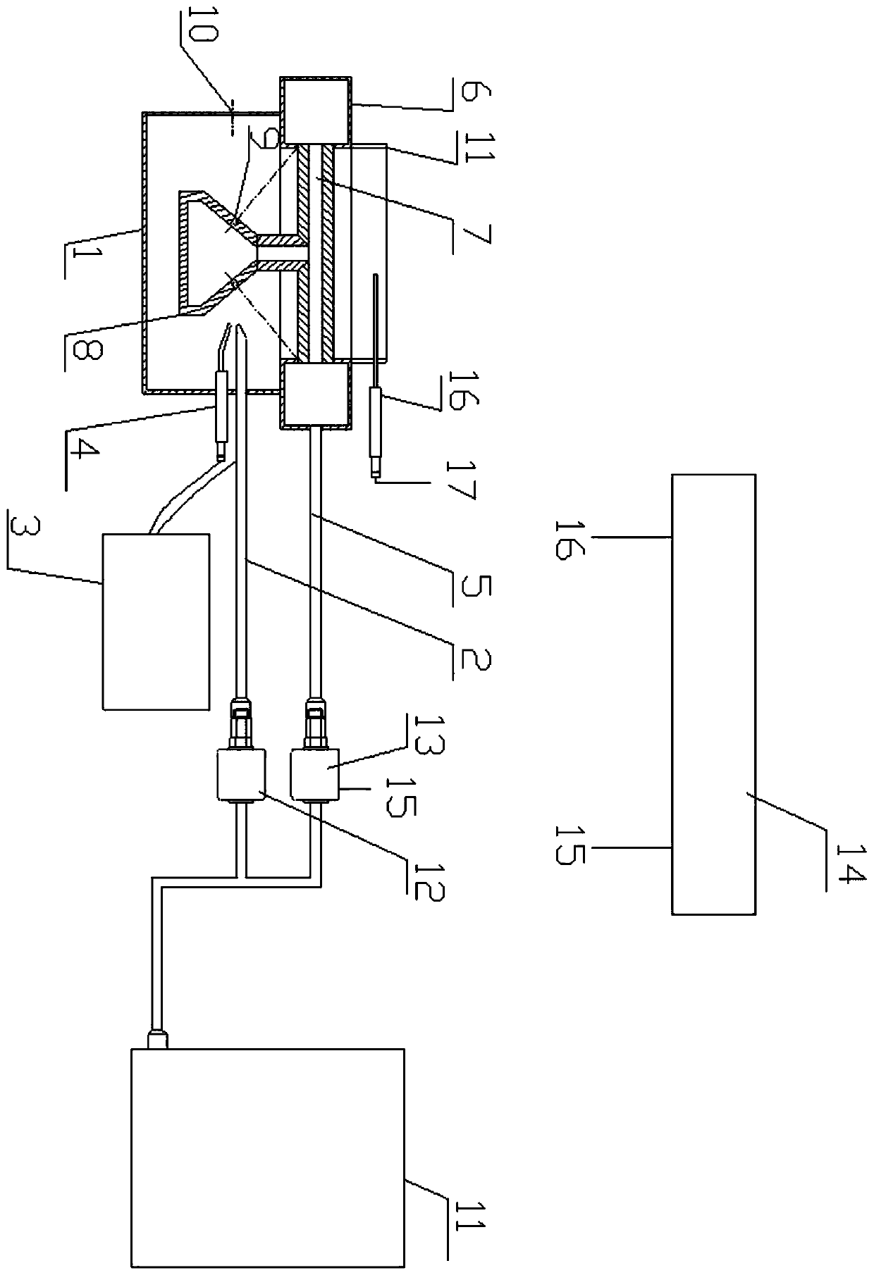
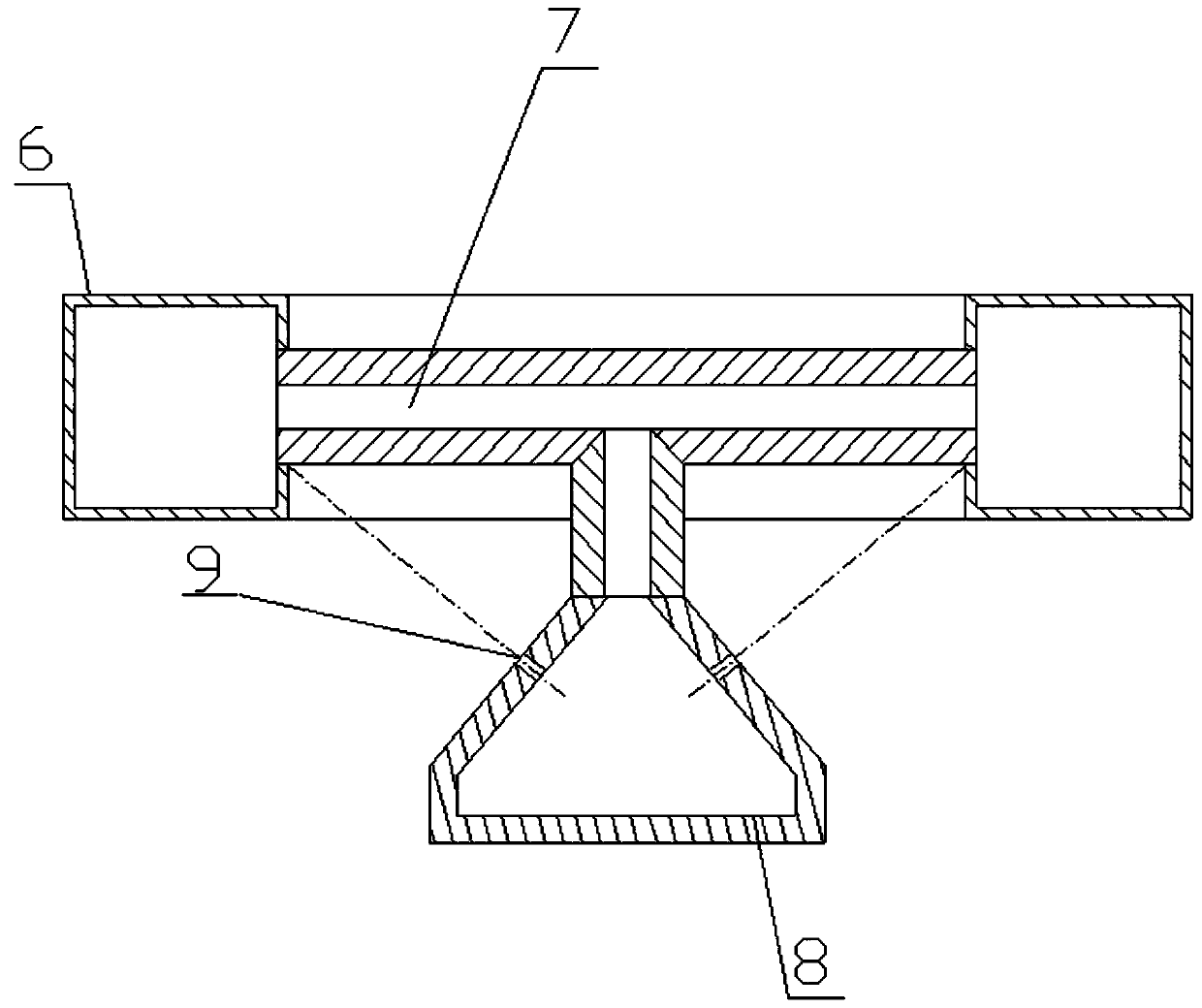
[0031] Such as figure 1 As shown, a small alcohol-based fuel self-heating vaporization combustion device that realizes micro-flow control includes an oil supply system, an ignition system and a burner 1 . The fuel supply system is connected to the burner 1 through an ignition oil pipe 2 and inputs liquid alcohol-based fuel into the burner 1, and the ignition system is connected to the interior of the burner 1 and input to the ignition oil pipe 2. Liquid alcohol-based fuel is pulsed to achieve ignition. The ignition system includes a pulse generator 3 and an ignition needle 4 . The pulse generator 3 is located outside the burner 1 . The ignition pin 4 is at a corresponding position in the burner 1 . One end of th...


PUM


Abstract

The invention relates to a small alcohol-based fuel self-heating, evaporating and combusting device for micro-flow control. The small alcohol-based fuel self-heating, evaporating and combusting devicecomprises an oil supply system, an igniting system and a combustor. The oil supply system is connected into the combustor through an igniting oil pipe and conveys liquid alcohol-based fuel into the combustor. The igniting system is connected into the combustor and carries out pulse discharging on the liquid alcohol-based fuel conveyed into the igniting oil pipe to realize igniting. The igniting system comprises a pulse generator and an igniting needle. The positive electrode and the negative electrode of the pulse generator are connected with the igniting needle and the igniting oil pipe correspondingly so that the liquid alcohol-based fuel output by the igniting oil pipe can be accurately ignited by pulse discharging flames. The small alcohol-based fuel self-heating, evaporating and combusting device has the advantages that the igniting oil pipe and the igniting needle form the positive electrode and the negative electrode for pulse igniting to conduct discharging, the liquid alcohol-based fuel output by the igniting oil pipe is accurately ignited by pulse ionic flames, and the igniting success rate is increased.

Description

technical field [0001] The invention relates to the field of alcohol-based fuel combustion, in particular to a small alcohol-based fuel self-heating vaporization combustion device for realizing micro-flow control. Background technique [0002] The Chinese invention patent with the patent number of 201822485648.7 discloses a small alcohol-based fuel self-heating vaporization combustion device, which uses the outer surface of the self-heating vaporization device as the ignition pulse point, and under the action of gravity, the liquid level of the liquid alcohol-based fuel rises to And the lower spread is expanded, and the heat generated by the vaporization and combustion of the alcohol-based fuel is used to heat the liquid alcohol-based fuel to obtain vaporization output. Above-mentioned patent is conducive to ignition success to a certain extent, but it also has the following defects: [0003] 1. The positive and negative poles of the pulse generator of the ignition system a...

Claims


Application Information

Patent Timeline
Patent Type & Authority Applications(China)
IPC IPC(8): F24C5/02F24C5/14F24C5/16F24C15/00
CPCF24C5/02F24C5/14F24C5/16F24C15/00
Inventor 陶积勇唐际钢梁永安秦国强卢昌锐莫宇生莫敏卢荣中
Owner GUILIN GANLONG ENVIRONMENTAL PROTECTION SCI & TECH CO LTD
Why Eureka
Try Eureka