A cooled infrared thermal imager

An infrared thermal imager and cooling technology, which is applied in the direction of instruments, scientific instruments, optical radiation measurement, etc., can solve the problems of large distance, large detector volume and poor quality

Active Publication Date: 2020-10-20
HUBEI JIUZHIYANG INFRARED SYST CO LTD
View PDF12 Cites 0 Cited by
  • Summary
  • Abstract
  • Description
  • Claims
  • Application Information

AI Technical Summary

Problems solved by technology

[0004] At present, due to the large size of the detector of the cooled thermal imaging camera, the lens group and the detector group are respectively fixed on the bottom plate during design, and the distance is relatively large. It takes a lot of money to strengthen the strength of the bottom plate to achieve optical axis consistency and parfocal performance, but performed poorly in environmental tests

Method used


Image

  • A cooled infrared thermal imager
  • A cooled infrared thermal imager
  • A cooled infrared thermal imager

Examples


Embodiment 1

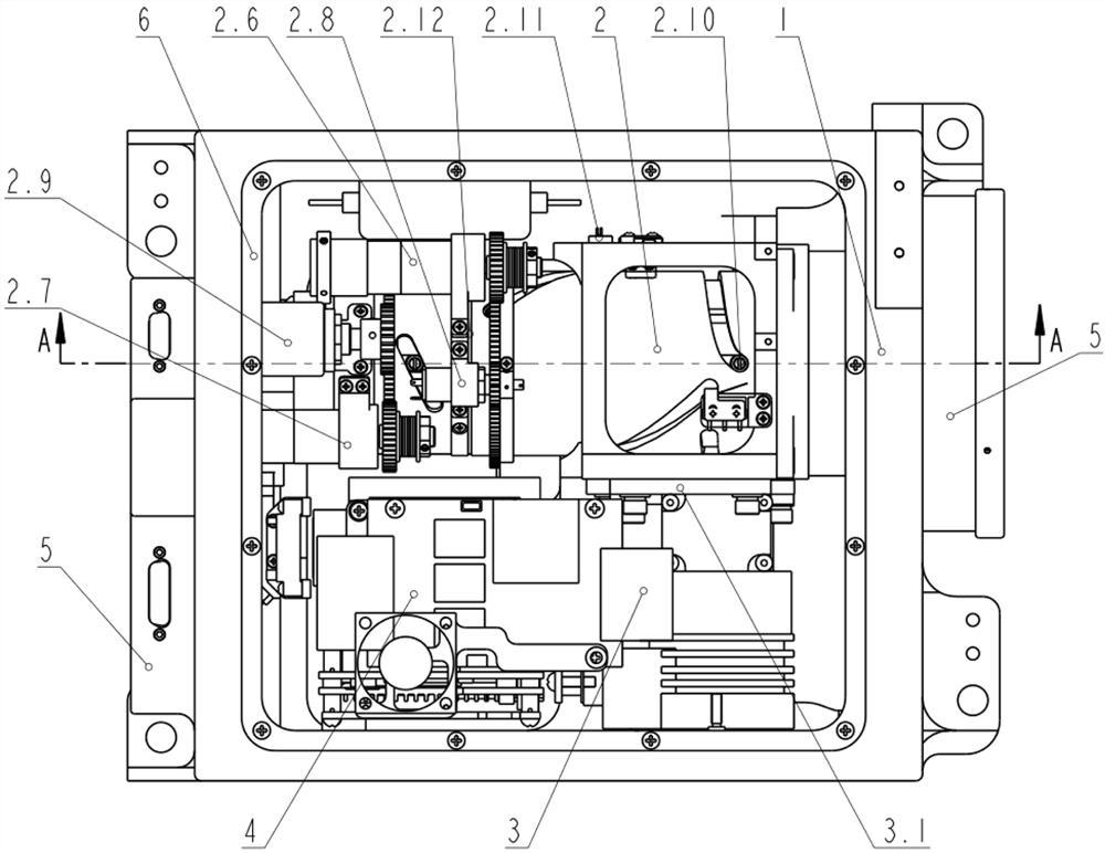
[0024] refer to figure 1 , figure 2 As shown, the cooling type thermal imager based on frame integration design disclosed by the present invention includes a main frame 1, a continuous zoom infrared lens 2, a cooling detector assembly 3, a circuit board group 4, a cover plate 5 and a conductive lining Pad 6; the continuous zoom infrared lens 2 is fixed on the main frame 1 through the flange, and the cooling detector assembly 3 is fixed on the main frame 1 through the detector trimming plate 3.1. The continuous zoom infrared lens 2 and the cooling detector assembly 3 are directly fixed on the main frame 1. Under various harsh environmental test conditions, only a small part of the main frame 1 needs to be strengthened to effectively improve the overall strength of the thermal imager. , to ensure optical axis consistency and parfocality during continuous zooming.

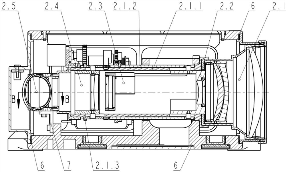
[0025] Described continuous zoom infrared lens 2 is made up of main objective lens group 2.1, zoom group 2.2, co...


PUM

PropertyMeasurementUnit
Cylindricityaaaaaaaaaa

Abstract

The invention discloses a cooling type infrared thermal imager, which comprises a main frame, a continuous zoom infrared lens, a cooling detector assembly, a circuit board group, a cover plate and a conductive gasket; the continuous zoom infrared lens and the cooling detector assembly are directly fixed On the main frame, the high stability of the optical axis of the continuous zoom thermal imager can be realized; the zoom potentiometer group is also set on the zoom mechanism, which can save the position of the zoom group and compensation group at any focal length; Equipped with focusing potentiometer group and temperature sensor, through the temperature sensor, the focus position of each temperature point of -40~60°C can be recorded in the circuit board group, so that each temperature point of -40~60°C can be adjusted at each focal length Clear imaging, consistent optical axis and parfocality can also be maintained under harsh vibration conditions. The continuous zoom infrared thermal imager designed by the present invention overcomes the disadvantages of easy jamming of the cam mechanism, poor optical axis consistency, poor parfocal performance, and low control precision, and has the advantages of compact structure and high reliability.

Description

technical field [0001] The invention belongs to the technical field of precision infrared instruments, and in particular relates to a cooling type infrared thermal imager based on an integrated frame design. Background technique [0002] The continuous zoom thermal imaging camera overcomes the problems that the single-field thermal imager cannot take into account the observation of far and near targets, and the multi-field thermal imager loses frames and loses the observation target during the zooming process. During the zooming process, the target is always clearly imaged, which is the best choice for tracking observation. [0003] The zoom mechanism of a continuous zoom thermal imaging camera is generally a cam mechanism or a ball screw mechanism. The cam mechanism has disadvantages such as easy sticking, poor optical axis consistency, poor parfocality, and low control precision, and the ball screw mechanism has disadvantages such as complex structure and heavy weight. A...

Claims


Application Information

Patent Timeline
Patent Type & Authority Patents(China)
IPC IPC(8): G01J5/00G01J5/02G01J5/06G01J5/08G03B13/34
CPCG01J5/00G01J5/0205G01J5/06G01J5/0806G03B13/34G01J2005/0077G01J2005/065
Inventor 李彪宋鹏飞熊涛吴耀李武彭章贤
Owner HUBEI JIUZHIYANG INFRARED SYST CO LTD
Why Eureka
Try Eureka