FC optical fibre splice tightening tool

A fiber optic connector and tool technology, applied in the field of fiber optic connection, can solve the problems of laborious installation, manpower, and time-consuming installation, and achieve the effect of avoiding damage and reducing interference

Active Publication Date: 2019-12-20
THE 44TH INST OF CHINA ELECTRONICS TECH GROUP CORP
View PDF9 Cites 1 Cited by
  • Summary
  • Abstract
  • Description
  • Claims
  • Application Information

AI Technical Summary

Problems solved by technology

[0003] However, compared with SC and LC connectors, FC-type optical fiber has the disadvantages of time-consuming and labor-intensive installation due to the use of threaded connectors. It is even more difficult for technicians to use it in a cabinet with a small space.
[0004] The technology for tightening the FC optical fiber connector is given in the Chinese patent "A Convenient Plug-in and Unpluggable FC Optical Fiber Connector and Its Operation Method" with the application number CN2017112217747. In this patent, the tightening force arm is increased by the clamp. The plug-in method replaces the threaded connection method, but it still uses manpower, and it clamps the FC connector by using two U-shaped locking clips, and the pliers need to be placed horizontally to rotate the clip, which requires too much space for rotation. Large, easily blocked by other optical fibers, not suitable for products with FC arrays or FC flanges with close spacing

Method used


Image

  • FC optical fibre splice tightening tool
  • FC optical fibre splice tightening tool

Examples


Embodiment Construction

[0021] In order to make the purpose, technical solutions and advantages of the present invention clearer, the technical solutions in the embodiments of the present invention will be clearly and completely described below in conjunction with the accompanying drawings. Obviously, the described embodiments are only part of the embodiments of the present invention, and Not all examples.

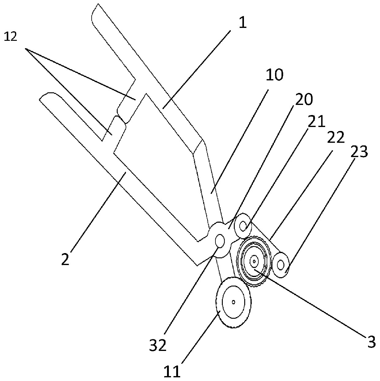
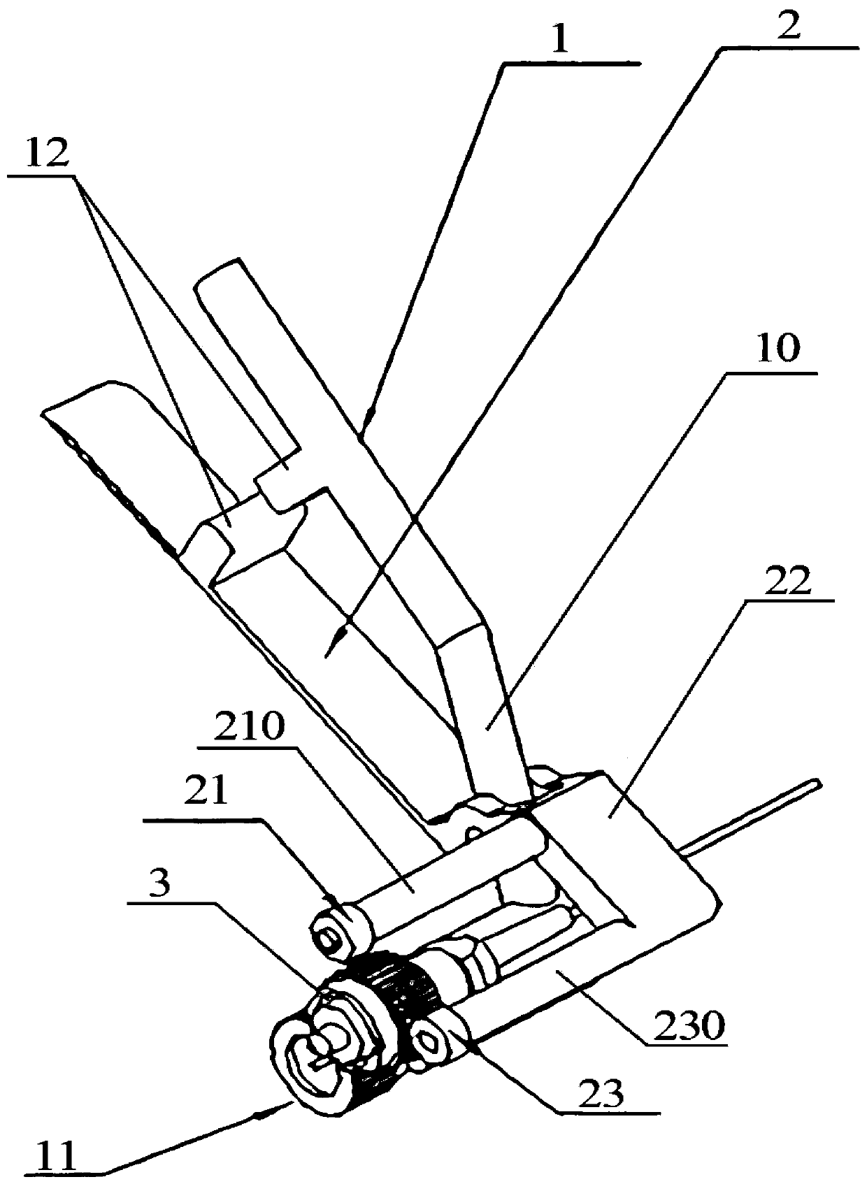
[0022] Reference as figure 1 and figure 2 As shown, a FC optical fiber connector tightening tool, the tightening tool at least includes a motor, a motor handle 1 and a gear handle 2; the end of the motor handle is provided with a first extension section 10 at an offset angle α, and the end of the gear handle The second extension section 20 is provided with an offset angle β; the first extension section 10 and the second extension section 20 are cross-hinged through the rotating shaft 32, and the end of the first extension section 10 is provided with a cylindrical groove to one side, so The mot...


PUM


Abstract

The invention belongs to the technical field of optical fibre connection, and relates to an FC optical fibre splice tightening tool. The tightening tool at least comprises a motor, a motor handle anda gear handle; a first extension section is arranged at the tail end of the motor handle; a second extension section is arranged at the tail end of the gear handle; the first extension section and thesecond extension section are crossed and hinged through a rotating shaft; a cylindrical groove is arranged towards one side on the tail end of the first extension section; the motor is fixed in the cylindrical groove; furthermore, the rotating shaft of the motor extends out of the cylindrical groove; a first gear is arranged on the rotating shaft of the motor; a first cylinder is arranged towardsone side on the tail end of the second extension section; a second gear is installed on the top of the first cylinder; a third extension section is arranged at the tail end of the second extension section; a second cylinder is arranged towards one side on the tail end of the third extension section; a third gear is installed on the top of the second cylinder; and an FC optical fibre splice is positioned among the various gears, and meshed with the various gears. The FC optical fibre splice tightening tool in the invention is driven by the motor; the manpower can be reduced; and furthermore, interference on the rest of optical fibres can be reduced.

Description

technical field [0001] The invention belongs to the technical field of optical fiber connection, and in particular relates to an FC optical fiber joint tightening tool. Background technique [0002] At present, optical fiber communication is widely used in various communication fields. As a physical part of the optical fiber communication system, optical fiber connectors have the function of connecting various optical fibers. At present, commonly used optical fiber (pigtail) connectors include: ST type, SC type, LC type, and FC type, among which FC type connectors are metal threaded connectors, which can be plugged in more times than plastic connectors, and are firm and dustproof. Advantages, so FC-type joints are widely used in practice. [0003] However, compared with SC and LC connectors, FC-type optical fiber has the disadvantages of time-consuming and labor-intensive installation due to the use of threaded connectors. It is even more difficult for technicians to use it...

Claims


Application Information

Patent Timeline
Patent Type & Authority Applications(China)
IPC IPC(8): G02B6/38
CPCG02B6/3898
Inventor 汤振华杨崇田思玉廖理刘建军
Owner THE 44TH INST OF CHINA ELECTRONICS TECH GROUP CORP
Why Eureka
Try Eureka