CNC (computer numerical control) machine tool clamp

A technology of CNC machine tools and fixtures, applied in the direction of clamping, clamping devices, manufacturing tools, etc., can solve the problems of stable clamping of plates with single-sided or multi-sided hypotenuses, and achieve the extension of the force arm and improve The effect of stable clamping

Inactive Publication Date: 2021-11-26
林凯
View PDF0 Cites 2 Cited by
  • Summary
  • Abstract
  • Description
  • Claims
  • Application Information

AI Technical Summary

Problems solved by technology

[0004] Based on the technical problem that it is difficult for existing fixtures to stably clamp plates with unilateral beveled sides or multi-sided beveled sides, this invention proposes a CNC numerical control machine tool fixture

Method used


Image

  • CNC (computer numerical control) machine tool clamp
  • CNC (computer numerical control) machine tool clamp
  • CNC (computer numerical control) machine tool clamp

Examples


Embodiment 1

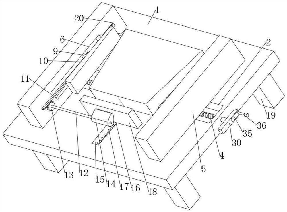
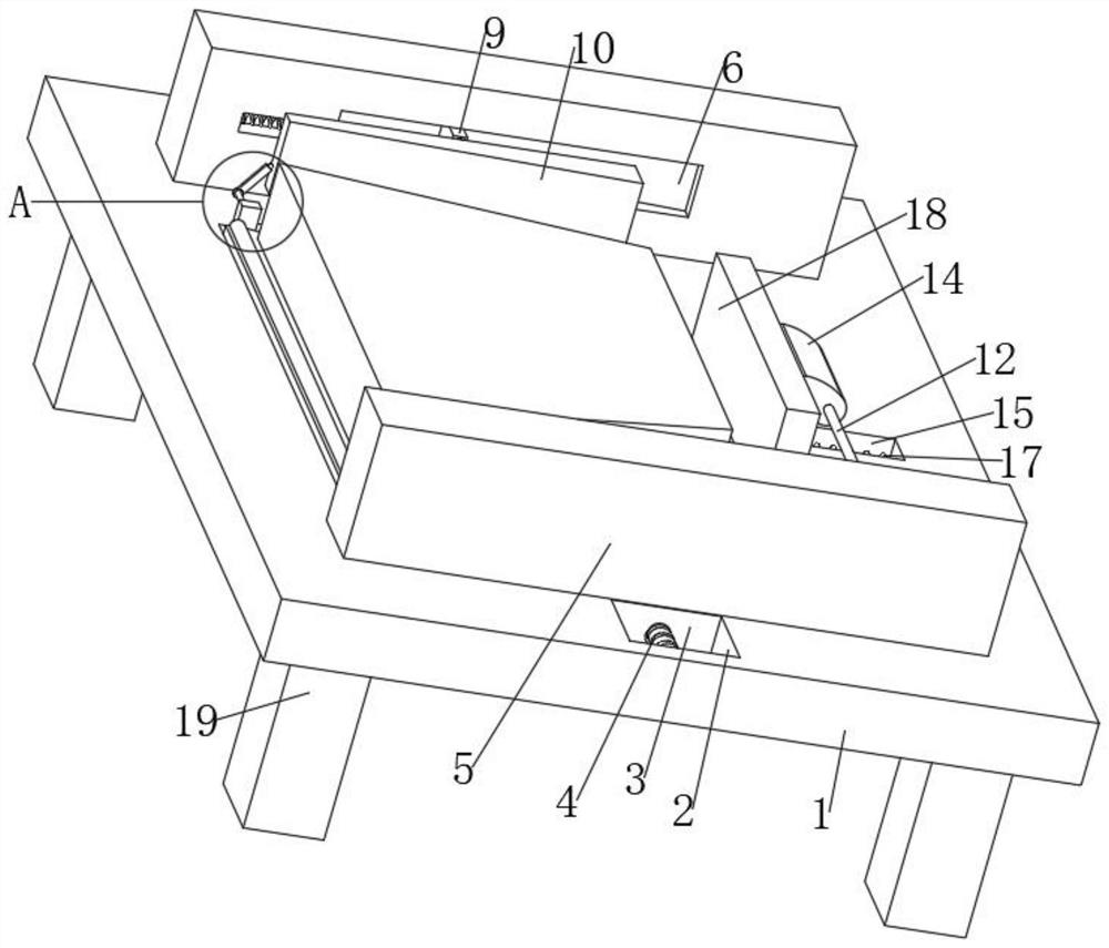
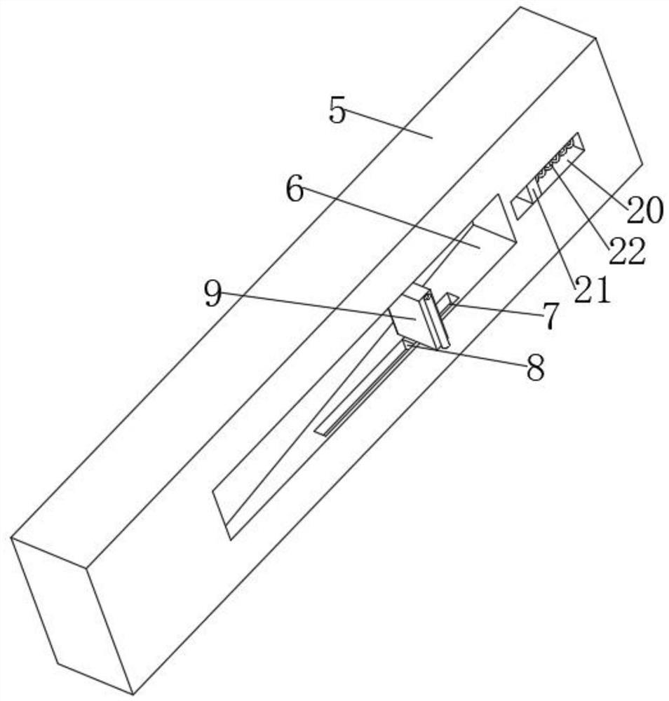
[0028] refer to Figure 1-5 , a CNC numerical control machine tool fixture, including a base plate 1, a plurality of legs 19 are fixed symmetrically by bolts on both sides of the bottom of the base plate 1, a first chute 2 is provided on the top of the base plate 1, and two symmetrical The distributed first slider 3, the same screw 4 is connected to the inner walls on both sides of the first chute 2 through bearing rotation, and a set of reverse threads are provided on the screw 4, the screw 4 and the first slider 3 are threadedly connected, the second The top of a slide block 3 is fixed with a mounting plate 5 by bolts, the inside of the mounting plate 5 is provided with a positioning groove 6, the cross section of the positioning groove 6 is set as a right-angled trapezoid, and the inner wall of the bottom of the positioning groove 6 is provided with a second chute 7, the second chute 7 The inner slide is connected with a second slider 8, the top of the second slider 8 is fi...

Embodiment 2

[0037] refer to figure 1 and Image 6 , a kind of CNC numerical control machine tool fixture, screw rod 4 side is fixed with handle 30 by bolt, and handle 30 outer side is provided with placement groove 31, is provided with extension mechanism in placement groove 31, extension mechanism is connected with extension rod 35, extension rod 35 The outer side is fixed with a handle 36 by a bolt, and the handle 36 can be held, and the extension rod 35 can be pulled out from the placement groove 31, so that the original length of the handle 30 can be extended, and the active force arm can be extended, so that the screw rod can be extended. 4 When rotating, the effect of labor saving can be achieved.

[0038] Further, the extension mechanism includes a limit spring 34, a limit groove 32 is opened on the side wall of the placement groove 31, and a limit block 33 is slidably connected in the limit groove 32, and the limit spring 34 is fixed to the limit block 33 and the limit block by b...


PUM


Abstract

The invention belongs to the technical field of clamps. A CNC (computer numerical control) machine tool clamp comprises a bottom plate, a first sliding groove is formed in the top of the bottom plate, two symmetrically distributed first sliding blocks are connected to the interior of the first sliding groove in a sliding mode, a screw is rotationally connected between the inner walls of the two sides of the first sliding groove through a bearing, the screw is in threaded connection with the first sliding groove, a mounting plate is fixed to the tops of the first sliding blocks through bolts, a positioning groove is formed in the inner side of the mounting plate, the section of the positioning groove is arranged to be a right trapezoid, a second sliding groove is formed in the inner wall of the bottom of the positioning groove, a second sliding block is connected to the interior of the second sliding groove in a sliding mode, a fixing block is fixed to the top of the second sliding block through a bolt, a clamping plate is hinged to the inner side of the fixing block, a transmission mechanism and a return mechanism are arranged on the mounting plate, and a front pressing mechanism and a rear pressing mechanism are arranged on the bottom plate. According to the CNC machine tool clamp, the screw is rotated to drive the mounting plate and the clamping plate to synchronously move; and when the clamping plate gradually makes contact with a plate, the clamping plate can rotate to gradually form an angle parallel to the bevel edge of the plate till the plate is attached and clamped.

Description

technical field [0001] The invention relates to the technical field of fixtures, in particular to a CNC numerical control machine tool fixture. Background technique [0002] Fixture refers to the device used to fix the processing object in the process of mechanical manufacturing so that it can occupy the correct position to accept construction or inspection. It is also called fixture. In a broad sense, any process in the process is used to quickly and The device that installs the workpiece conveniently and safely can be called a fixture. CNC machine tool (numerical control machine tool) is an automatic machine tool equipped with a program control system, which can make the machine tool move and process parts according to the programmed program. CNC machine tools integrate machinery, automation, computer, microelectronics and other technologies to solve the processing problems of complex, precise and small batch parts. It is a flexible and high-efficiency automatic machine to...

Claims


Application Information

Patent Timeline
Patent Type & Authority Applications(China)
IPC IPC(8): B23Q3/06
CPCB23Q3/06B23Q3/062B23Q2703/10
Inventor 林凯
Owner 林凯
Why Eureka
Try Eureka