Cutting device for waste cable recycling

A technology for waste cables and cables, applied in the field of wires and cables, can solve the problems of manpower consumption and low efficiency, and achieve the effect of reducing labor intensity, ensuring cutting effect and increasing applicability

Active Publication Date: 2019-12-20
安徽飞马电缆有限公司
View PDF9 Cites 9 Cited by
  • Summary
  • Abstract
  • Description
  • Claims
  • Application Information

AI Technical Summary

Problems solved by technology

[0003] The purpose of the present invention is to solve the problem of labor-intensive an

Method used


Image

  • Cutting device for waste cable recycling
  • Cutting device for waste cable recycling
  • Cutting device for waste cable recycling

Examples


Embodiment 1

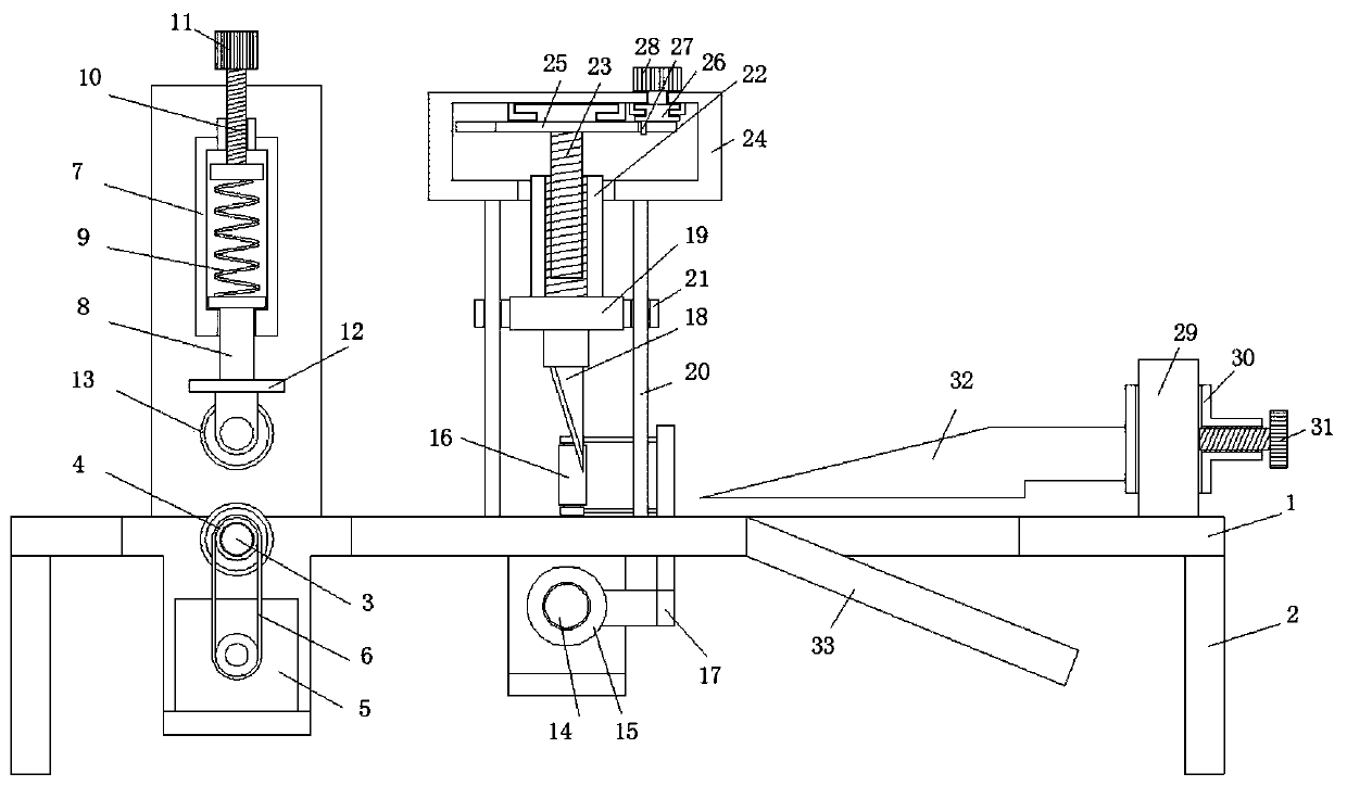
[0022] refer to Figure 1-3 , a cutting device for recycling waste cables, comprising a workbench 1, the four corners of the bottom of the workbench 1 are provided with feet 2, the top side of the workbench 1 is provided with a cable drive mechanism, and the cable drive mechanism includes a bottom roller 4 and a top roller 13. The worktable 1 is provided with a groove 1, and the inner wall of the groove 1 is fixedly connected with the horizontal shaft 3, and the bottom roller 4 is rotatably set on the outside of the horizontal shaft 3, and the top side of the workbench 1 is provided with a sliding cylinder 7. The cylinder 7 is located vertically above the groove 1. A slide rod 8 is slidably connected in the slide cylinder 7. The bottom end of the slide rod 8 extends to the bottom side of the slide cylinder 7 and is fixedly connected with a connecting plate 12. The top roller 13 is rotatably connected to the On the bottom side of the connecting plate 12, the top of the sliding ...

Embodiment 2

[0025] like Figure 1-3 As shown, this embodiment is basically the same as Embodiment 1. Preferably, the outer sides of the bottom roller 4 , the top roller 13 and the side rollers 16 are all covered with rubber sleeves.

[0026] In this embodiment, the frictional force is made larger to ensure the driving of the cable.

Embodiment 3

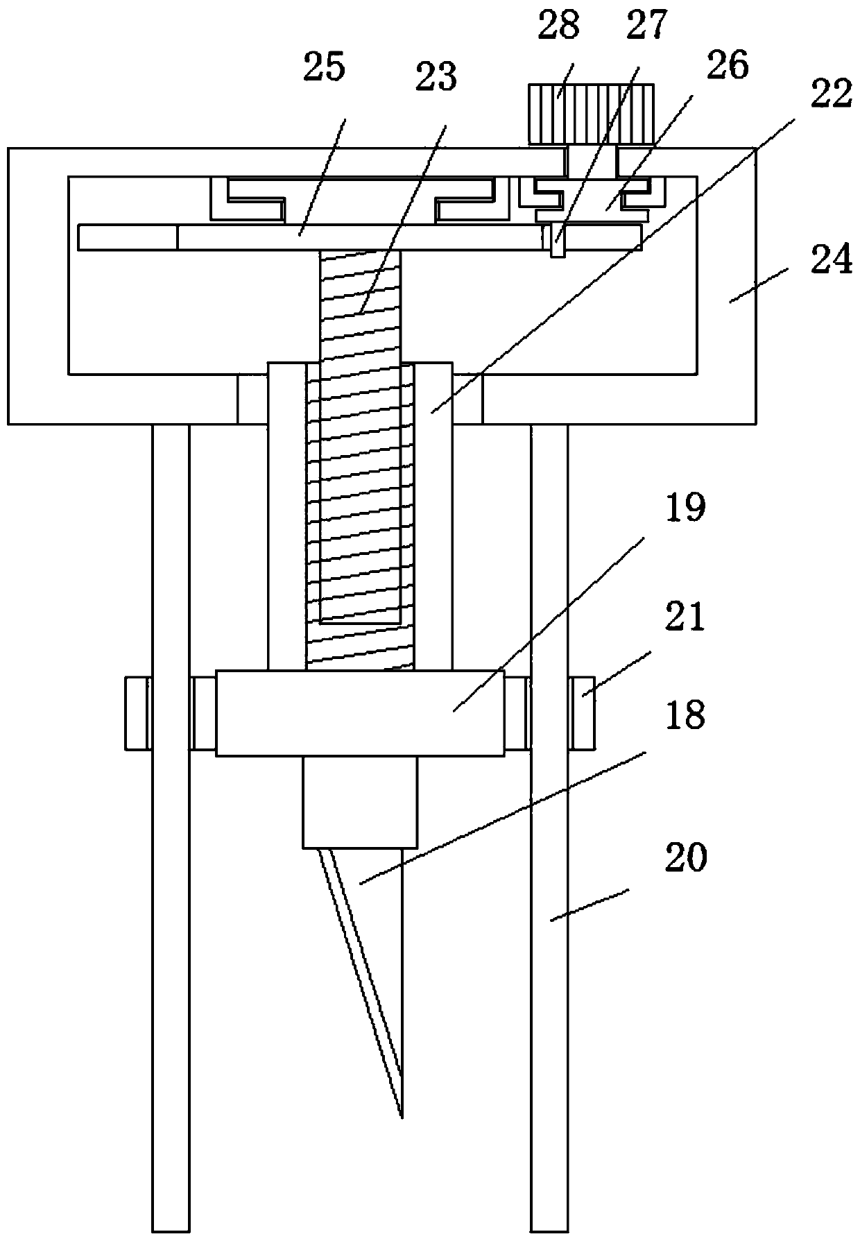
[0028] like Figure 1-3 As shown, this embodiment is basically the same as Embodiment 1, preferably, the bottom end of the cutter 18 extends to between the two side rollers 16 .

[0029] In this embodiment, the distance between the cutter 18 and the side rollers 16 on both sides is the same.


PUM


Abstract

The invention discloses a cutting device for waste cable recycling. The cutting device comprises a workbench, wherein support legs are arranged at four corners of the bottom of the workbench, a cabledriving mechanism is arranged at a top side of the workbench and comprises a bottom roller and a top roller, a first groove is formed in the workbench, a horizontal shaft is fixedly connected betweeninner walls of the first groove, the bottom roller rotatably sleeves an outer side of the horizontal shaft, a sliding cylinder is erected at a top side of the workbench and is arranged above a vertical part of the first groove, a sliding rod is connected to the sliding cylinder in a sliding way, a bottom end of the sliding rod extends to a bottom side of the sliding cylinder and is fixedly connected with a connection plate, the top roller is rotatably connected to a bottom side of the connection plate, a threaded hole is formed in a top end of the sliding cylinder, the top end of the sliding cylinder is in threaded connection with a threaded push rod, and a pressurization spring is arranged between the threaded push rod and the top end of the sliding rod. By the cutting device, the cuttingeffect is ensured, the cutting device is high in applicability, labor is saved, the production efficiency is improved, and the application demand of people in production life is satisfied.

Description

technical field [0001] The invention relates to the technical field of wires and cables, in particular to a cutting device for recycling waste cables. Background technique [0002] The existing slitting device for waste cable recycling has multiple wire inlets, so as to meet the slitting of wires and cables of different specifications, but the types of specifications are limited, and the types that can be slit are limited, and waste cables are used for a long time During the process, due to different degrees of oxidation and damage of the outer sheath and the inner metal wire, there is a certain error with the original size. When using the existing equipment for cutting, it will cause damage to the cutter, or the cable sheath will not be cut properly. Thoroughly, but in the follow-up, it is necessary to manually separate the cable sheath and cable inner core. It is more difficult to manually separate cables that are not completely separated, which greatly increases people's ...

Claims


Application Information

Patent Timeline
IPC IPC(8): H01B15/00
CPCH01B15/006Y02W30/82
Inventor 邹艳娜佟仁友
Owner 安徽飞马电缆有限公司
Why Eureka
Try Eureka