
Thin-tube laser beam quality self-compensation method and device

A laser beam quality and self-compensation technology, which is applied to laser components, lasers, phonon exciters, etc., can solve problems such as limited ability to improve beam quality and complex systems

Active Publication Date: 2019-12-20
SICHUAN UNIV
View PDF3 Cites 1 Cited by
  • Summary
  • Abstract
  • Description
  • Claims
  • Application Information

AI Technical Summary

Problems solved by technology

[0005] In order to solve the problem of limited beam quality improvement ability and complex system faced by the existing zigzag optical path thin tube solid-state laser device, the present invention proposes a thin tube laser beam quality self-compensation method and device

Method used


Image

  • Thin-tube laser beam quality self-compensation method and device
  • Thin-tube laser beam quality self-compensation method and device
  • Thin-tube laser beam quality self-compensation method and device

Examples


Embodiment Construction

[0017] The present invention will be further described in detail below in conjunction with the accompanying drawings and specific embodiments. It must be pointed out that the described embodiments are only used to further describe the present invention, and do not mean any limitation to the protection scope of the present invention.

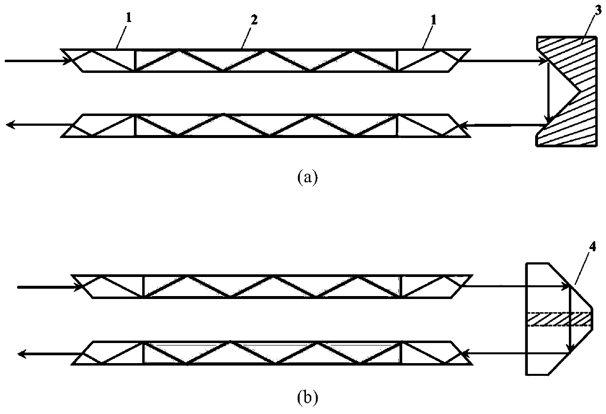
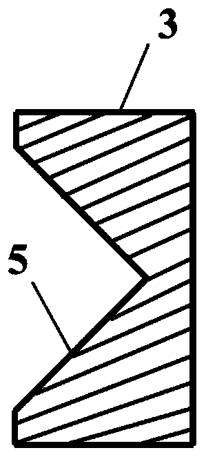
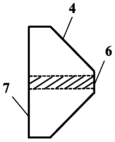
[0018] A thin-tube laser beam quality self-compensation method and device described in the present invention, the optical path for realizing the self-compensation method is as follows figure 1 shown. Including zigzag optical path thin tube laser device: 1 non-doped end cap, 2 doped thin tube, also includes zigzag optical path thin tube solid-state laser device Beam quality compensation device: 3 right-angle inner cone mirrors or 4 total reflection right-angle Tapered devices. Among them, the reflective surface of the right-angle inner cone mirror is coated with a high-reflection film system, and the incident / exit end surface of the total reflect...


PUM


Abstract

The invention relates to a thin-tube laser beam quality self-compensation method and device. According to the method, a right-angle conical surface reflection device is added to one end of a thin tubegain medium of a thin tube solid laser, so that light emitted by the thin tube medium returns to a thin tube at a radial symmetry point of an emitting point of the light and is reversely propagated,wavefront distortion caused by static errors of the thin tube is self-compensated, and the quality of a light beam is effectively improved.

Description

technical field [0001] The invention relates to a high-power solid-state laser beam quality self-compensation technology, in particular to a thin-tube laser beam quality self-compensation method and device. Background technique [0002] Solid-state laser is a high-efficiency, stable and portable high-quality laser light source, which has a wide range of applications in military, industrial, medical and communication fields. Compared with traditional solid-state lasers such as slabs, rods, and sheets, zigzag optical path thin-tube solid-state lasers have the advantages of compact structure, large effective gain volume, strong heat transfer capability, and easy launch. It is expected to become a research hotspot in the next generation of solid-state laser technology. Beam quality control is one of the core technical issues in the field of solid-state lasers. Although the thin-tube solid-state laser device with zigzag optical path can obtain a good dynamic thermal distortion c...

Claims


Application Information

Patent Timeline
Patent Type & Authority Applications(China)
IPC IPC(8): H01S3/081
CPCH01S3/0816
Inventor 张彬田博宇钟哲强孙年春张小民
Owner SICHUAN UNIV
Learn More