
Two-dimensional thermal temperature difference type wind speed sensor and ambient self-compensation method for same

A technology of wind speed sensor and thermal temperature difference, which is applied in the direction of measuring fluid speed, instrument, speed/acceleration/impact measurement by using thermal variables, which can solve the problem of low detection rate of thermal temperature difference wind speed sensor, and achieve the improvement of thermal response rate and lateral Fast conduction reduces and improves the effect of wind speed and direction detection rate

Pending Publication Date: 2019-04-19
HARBIN UNIV OF SCI & TECH
View PDF1 Cites 0 Cited by
  • Summary
  • Abstract
  • Description
  • Claims
  • Application Information

AI Technical Summary

Problems solved by technology

[0005] The present invention proposes a two-dimensional thermal temperature difference wind speed sensor and its environment self-compensation method to solve the problem of low detection rate of the existing aluminum nitride-based thermal temperature difference wind speed sensor

Method used


Image

  • Two-dimensional thermal temperature difference type wind speed sensor and ambient self-compensation method for same
  • Two-dimensional thermal temperature difference type wind speed sensor and ambient self-compensation method for same
  • Two-dimensional thermal temperature difference type wind speed sensor and ambient self-compensation method for same

Examples


Embodiment

[0038] Embodiment: combine below Figure 1 to Figure 5 This embodiment will be described in detail.

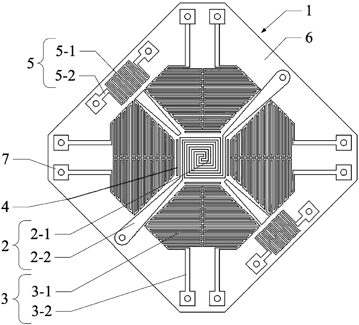
[0039] The two-dimensional thermal temperature difference wind speed sensor described in this embodiment includes a substrate 1, a heating electrode 2, four temperature detection electrodes 3, four thermal isolation grooves 4 and two ambient temperature self-compensation electrodes 5;

[0040] The substrate 1 is octagonal and made of low thermal conductivity material. On the top surface of the substrate 1 is laid a thermally conductive medium layer 6, heating electrodes 2, four temperature detection electrodes 3 and two ambient temperature self-compensation electrodes 5 are all arranged on the heat conduction medium layer 6;

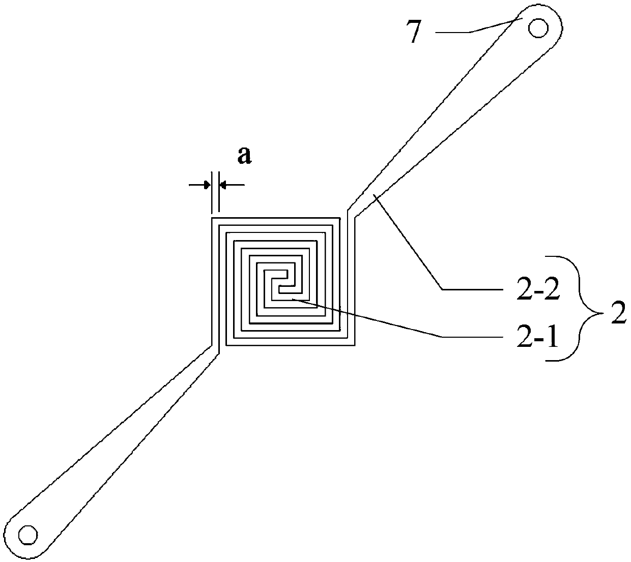
[0041] The heating electrode 2 includes a heating electrode body 2-1 and two lead-out electrodes 2-2. The heating electrode body 2-1 has a square coiled spiral structure, and is arranged at the center of the heat-conducting medium layer 6. The two lead-...


PUM

PropertyMeasurementUnit
Thicknessaaaaaaaaaa
Thicknessaaaaaaaaaa
Thicknessaaaaaaaaaa

Abstract

The invention discloses a two-dimensional thermal temperature difference type wind speed sensor and an ambient self-compensation method for the same, and belongs to the field of wind speed sensors. Bythe aid of the two-dimensional thermal temperature difference type wind speed sensor and the ambient self-compensation method, the problem of low detection speeds of existing aluminum nitride base thermal temperature difference type wind speed sensors can be solved. The two-dimensional thermal temperature difference type wind speed sensor is characterized in that a heat conduction medium layer islaid on a substrate with low heat conductivity, and a heating electrode, four temperature detection electrodes and two ambient temperature self-compensation electrodes are arranged on the heat conduction medium layer. A square heating electrode body is arranged in the center of the heat conduction medium layer, four fan-shaped temperature detection electrode bodies are arranged on the periphery of the heating electrode body, and two ambient temperature self-compensation electrode bodies are arranged at two opposite edges of the heating medium layer. Each electrode body is provided with two extraction electrodes. The ambient self-compensation method includes determining ambient temperature values according to resistance values of the two ambient temperature self-compensation electrodes; regulating voltage frequencies of two ends of the heating electrode according to change of the ambient temperature values so as to allow temperature fields of the two-dimensional thermal temperature difference type wind speed sensor to be constant.

Description

technical field [0001] The invention relates to a wind speed sensor, in particular to a two-dimensional thermal temperature difference wind speed sensor and an environment self-compensation method thereof. Background technique [0002] Wind speed sensors are widely used in wind power generation, mine ventilation, solar power generation wind direction control and gas flow monitoring and other fields. In recent years, with the continuous development of MEMS technology, thermal temperature difference wind speed sensors have also made new breakthroughs and developments. [0003] The Chinese invention patent with the authorized announcement number CN 102998479 B discloses a two-dimensional wind speed and direction sensor with an aluminum nitride-based integrated array structure, which belongs to the thermal temperature difference wind speed sensor. The sensor solves the shortcomings of the wind speed sensor integrating the principle of thermal temperature difference using a sili...

Claims


Application Information

Patent Timeline
IPC IPC(8): G01P1/00G01P1/02G01P5/10
CPCG01P1/006G01P1/026G01P5/10
Inventor 赵文杰徐丹陈寅生刘丛宁李鹏飞
Owner HARBIN UNIV OF SCI & TECH
Learn More