Fast response phase change temperature control device

A temperature control device and fast-response technology, which can be applied in the direction of using electric mode for temperature control, auxiliary controller with auxiliary heating device, etc., which can solve the problems of low response rate, low module rate, high cost, etc. Heat transfer area, increase safety margin, and improve the effect of thermal conductivity

Active Publication Date: 2020-03-31
10TH RES INST OF CETC
View PDF5 Cites 0 Cited by
  • Summary
  • Abstract
  • Description
  • Claims
  • Application Information

AI Technical Summary

Problems solved by technology

[0010] The low thermal conductivity of phase change materials in traditional phase change temperature control devices limits them to be placed around heat-generating devices / equipment to compensate for the low response rate caused by their low thermal conductivity. is feasible
For the current bomb-borne and space-borne platforms with very compact structural space and irregular shapes, the heat generation of temperature-controlled devices / equipment is increasing, and the filling amount of phase-change materials is also increasing. At that time, the traditional phase change temperature control device is useless
[0011] d) Poor versatility and low module rate
[0012] Due to the low thermal expansion rate of the phase change material itself in the traditional phase change temperature control device, the shape and position of the heat source must be taken into account when designing the temperature control device. Usually, the phase change material is packaged with a metal energy storage cavity and then attached to the heating component The heat-generating components are wrapped on the side or with phase-change materials and then packaged as a whole. These designs make the structure of the temperature control device very different, and it is impossible to form a series of products. The versatility is poor, the module rate is low, and the cost of component maintenance and replacement is huge.

Method used


Image

  • Fast response phase change temperature control device
  • Fast response phase change temperature control device
  • Fast response phase change temperature control device

Examples


Embodiment Construction

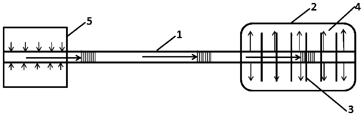
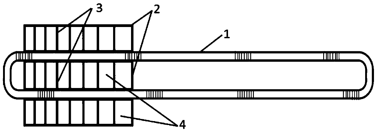
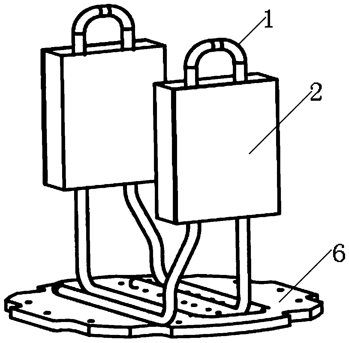
[0028] refer to figure 1 , figure 2 . In the embodiment described below, the fast-response phase change temperature control device includes: a pulsating heat pipe PHP1 that conducts heat transfer through the phase change of the internal liquid working fluid, and a metal energy storage cavity 2 filled with a high thermal conductivity phase change material 4 for improving Fin grid structure 3 with thermal response rate, high thermal conductivity phase change material 4 for storing heat.

[0029] When the temperature-controlled device / equipment 5 is working, the heat emitted by it is transferred to the hot end of the pulsating heat pipe PHP1, and the liquid medium filled in the hollow metal loop pipe undergoes a phase change, and the heat is brought to the cold end of the pulsating heat pipe PHP1, and transferred To the rib grid structure 3, it is absorbed by the high thermal conductivity phase change material 4 in the metal energy storage cavity 2 to prevent the temperature-c...


PUM


Abstract

The objective of the invention is to provide a fast-response phase change temperature control device which is fast in thermal response speed, suitable for installation in narrow space, and capable of achieving a stable temperature control function for electronic and optical heating devices / equipment. The temperature control device is characterized in that a metal energy storage cavity with a fin grid structure is filled with highly thermal conductive phase change materials; one end of a pulse heat pipe PHP passes the metal energy storage cavity and the other end of the PHP is connected with a to-be-controlled device / equipment. When the to-be-controlled device / equipment works, heat is transmitted to the hot end of the pulse heat pipe PHP and is absorbed by the highly thermal conductive phase change materials arranged in the fin grid structure. When the to-be-controlled device / equipment s in a low-temperature environment, the highly thermal conductive phase change materials discharge the absorbed heat energy during work of the to-be-controlled device / equipment, and transmits the heat energy to the to-be-controlled device / equipment through the pulse heat pipe PHP for achieving thermal insulation.

Description

technical field [0001] The invention relates to a fast-response phase-change temperature control device, in particular to a fast-response phase-change temperature control device suitable for missile-borne and space-borne equipment with high power, short-time work and strictly controlled structural dimensions. Background technique [0002] With the advancement of microwave technology, phased array antennas are developing toward high integration, high power consumption (heat consumption up to 2000W), and miniaturization, which puts forward higher requirements for the thermal design of the antenna. Phased array antennas have the characteristics of limited high-power working time, large heat generation during work, and lack of heat dissipation environment. However, due to factors such as structural size and total energy carrying capacity, they cannot provide forced air cooling, liquid cooling, and low-temperature refrigeration temperature control. And other active thermal contro...

Claims


Application Information

Patent Timeline
Patent Type & Authority Patents(China)
IPC IPC(8): G05D23/30
CPCG05D23/30
Inventor 吕倩何智航杨飞
Owner 10TH RES INST OF CETC
Why Eureka
Try Eureka