Motor cooling component, control method, control device and electrical equipment
A technology of electrical equipment and components, which is applied in the field of control methods, control devices, electrical equipment, and motor cooling components, and can solve problems such as the inability of the motor to dissipate heat, affect the operating life of the motor, and affect the reliability and life of the dryer as a whole. Guaranteed operating life, guaranteed reliability and effects of operating life
- Summary
- Abstract
- Description
- Claims
- Application Information
AI Technical Summary
Problems solved by technology
Method used
Image

Examples
Embodiment Construction
[0076] In order to make the purpose, technical solution and advantages of the present application clearer, the technical solution of the present application will be described in detail below. Apparently, the described embodiments are only some of the embodiments of this application, not all of them. Based on the embodiments in the present application, all other implementation manners obtained by persons of ordinary skill in the art without creative efforts fall within the protection scope of the present application.
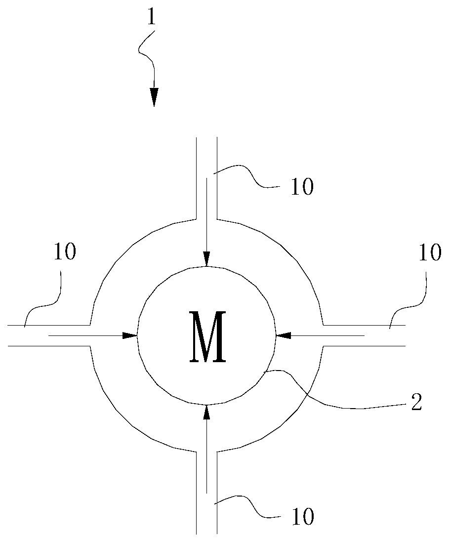
[0077] figure 1 A schematic structural diagram of a motor cooling assembly provided for an embodiment of the present application, such as figure 1 As shown, the motor cooling assembly 1 includes:
[0078] A plurality of cold air ducts 10, wherein each of the cold air ducts 10 can output one way of cold air that can reach the motor 2, and the cold air output by each of the cold air ducts 10 arrives at different positions on the motor 2, Moreover, the multiple c...
PUM
 Abstract
Description
Claims
Application Information
 - R&D
- Intellectual Property
- Life Sciences
- Materials
- Tech Scout
- Unparalleled Data Quality
- Higher Quality Content
- 60% Fewer Hallucinations
Browse by: Latest US Patents, China's latest patents, Technical Efficacy Thesaurus, Application Domain, Technology Topic, Popular Technical Reports.
© 2025 PatSnap. All rights reserved.Legal|Privacy policy|Modern Slavery Act Transparency Statement|Sitemap|About US| Contact US: help@patsnap.com