Humidification machine of breathing apparatus and control method of humidification machine

A humidifier and ventilator technology, applied in the field of ventilators, can solve the problems of increased ventilator pipeline infection, failure to work, and suffocation of patients

Inactive Publication Date: 2019-12-24
THE FIRST AFFILIATED HOSPITAL OF CHONGQING MEDICAL UNIVERSITY
View PDF13 Cites 0 Cited by
  • Summary
  • Abstract
  • Description
  • Claims
  • Application Information

AI Technical Summary

Problems solved by technology

Disconnecting the ventilator tube to add water and using a syringe to add water both need to disconnect the ventilator tube, which affects the patient's treatment, and at the same time increases the chance of ventilator tube infection due to repeated disconnection of the circuit
When using the infusion set to add water, manual care is required. However, in clinical practice, sometimes the doctors and nurses are too busy to add water, resulting in a "dry burn". As a result, the gas inhaled by the patient is not only not humidified, but also easily causes damage to the humidification tank. After the medical staff opened the infusion set to add water to the humidification tank, they were disturbed by other things. They did not pay attention to the amount of water added or forgot, which often caused too much water to be added, causing the water in the humi

Method used


Image

  • Humidification machine of breathing apparatus and control method of humidification machine
  • Humidification machine of breathing apparatus and control method of humidification machine
  • Humidification machine of breathing apparatus and control method of humidification machine

Examples


Embodiment Construction

[0024] The specific implementation manner of the present invention will be described in more detail below with reference to schematic diagrams. Advantages and features of the present invention will be apparent from the following description and claims. It should be noted that all the drawings are in a very simplified form and use imprecise scales, and are only used to facilitate and clearly assist the purpose of illustrating the embodiments of the present invention.

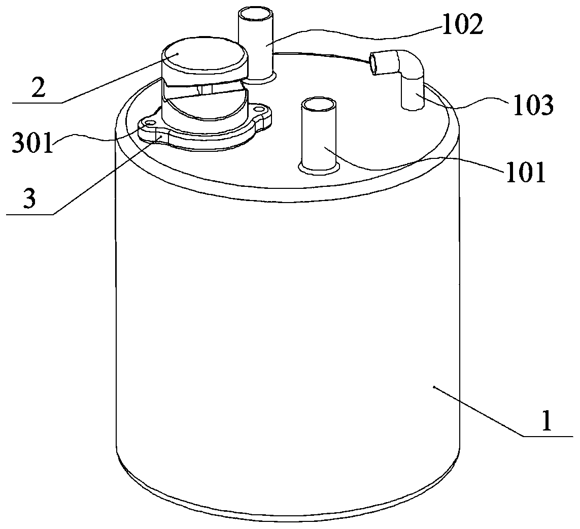
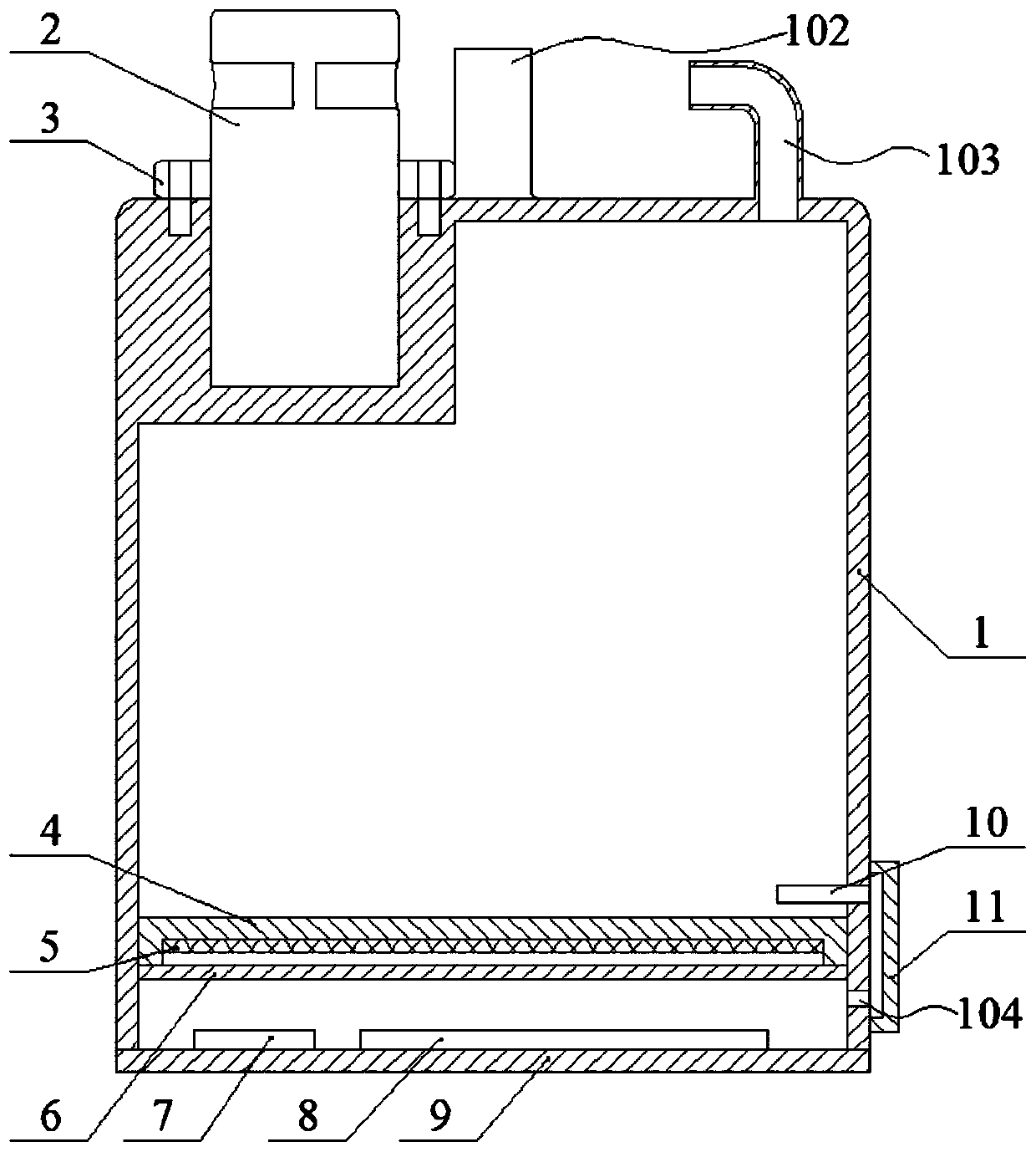
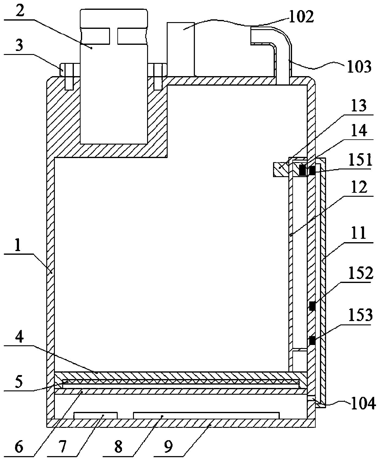
[0025] figure 1 It is a schematic diagram of a humidifier provided by an embodiment of the present invention, figure 2 It is a schematic cross-sectional view of a humidifier provided by an embodiment of the present invention, such as figure 1 with figure 2 As shown, the humidifier includes: a humidification tank 1, a pinch valve 2, a silicone tube (not shown), a sealing cover 4, a heater 5, a buzzer 7, a circuit board 8, an end cover 9 and Water level detection device. The humidification tank 1 is a cavity...


PUM


Abstract

The invention discloses a humidification machine of a breathing apparatus and a control method of the humidification machine. The humidification machine comprises a humidification tank, a pipe clamping valve, a silicone pipe, a buzzer, a circuit board, an end cover and a water level detection device, wherein a water filling pipe is arranged at one end of the humidification tank; the pipe clampingvalve is arranged at one end adjacent to the water filling pipe, of the humidification tank; the silicone pipe clamped by the pipe clamping valve is connected with the water filling pipe; the end cover is arranged at the other end of the humidification tank; the buzzer and the circuit board are arranged on the inner side of the end cover. The control method of the humidification machine comprisesthe following steps that water level is detected by the water level detection device; when a low water level is detected, the circuit board controls the pipe clamping valve to communicate with the silicone pipe for water injection; and when a high water level is detected, the circuit board controls the pipe clamping valve to pinch off the silicone pipe to stop water injection. The humidification machine provided by the invention can automatically control the humidification machine to add water, so that the situations that the added water of the humidification machine is too much or insufficient, and the treatment of the patient is influenced are avoided.

Description

technical field [0001] The invention relates to the technical field of ventilators, in particular to a humidifier of a ventilator and a control method thereof. Background technique [0002] Ventilator is a vital medical equipment that can prevent and treat respiratory failure, save and prolong the life of patients. The humidifier is an important part of the ventilator. When critically ill patients use the ventilator to assist ventilation, the gas sent by the ventilator is dry and cold. The dry and cold gas enters the trachea and damages lung function, resulting in a reduction in the number of cilia, dysfunction, and damage to the lungs. Alveolar surfactant, sputum viscous block the airway, increase the incidence of lung infection, etc. Therefore, it is necessary to heat and humidify the inhaled air through a humidifier. [0003] The humidifier needs to add water continuously with the consumption of sterilized water for injection during operation. The humidifier water adding...

Claims


Application Information

Patent Timeline
IPC IPC(8): A61M16/16
CPCA61M16/162
Inventor 吕顺巧米洁
Owner THE FIRST AFFILIATED HOSPITAL OF CHONGQING MEDICAL UNIVERSITY
Why Eureka
Try Eureka