
Laser three-dimensional forming process detecting method and system and application thereof

A technology of laser three-dimensional forming and process inspection, which is applied in the direction of improving process efficiency, improving energy efficiency, and additive manufacturing, and can solve problems such as not being suitable for industrial production sites, difficult, high use costs, and high site requirements

Active Publication Date: 2019-12-24
中国兵器装备集团自动化研究所有限公司
View PDF9 Cites 13 Cited by
  • Summary
  • Abstract
  • Description
  • Claims
  • Application Information

AI Technical Summary

Problems solved by technology

However, in these control methods, there is a common fatal problem. The detection process is mostly after the forming is completed, and it is not real-time detection during the printing process, but between layers or after completion; in-situ X-ray technology can be used for online detection. However, the cost of use and site requirements are high, and it is not suitable for industrial production sites
This makes it difficult to fundamentally improve the quality level of additive manufacturing sites and to achieve large-scale practical applications in the industrial field

Method used


Image

  • Laser three-dimensional forming process detecting method and system and application thereof
  • Laser three-dimensional forming process detecting method and system and application thereof
  • Laser three-dimensional forming process detecting method and system and application thereof

Examples


Embodiment 1

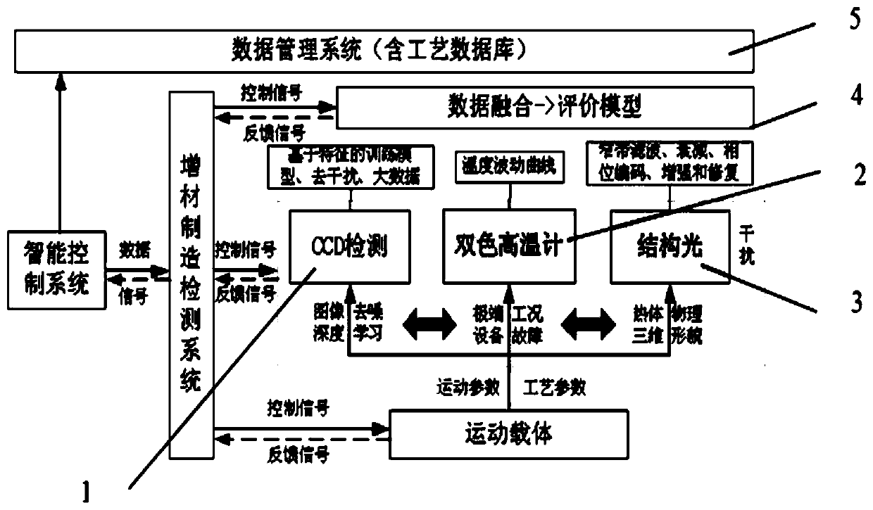
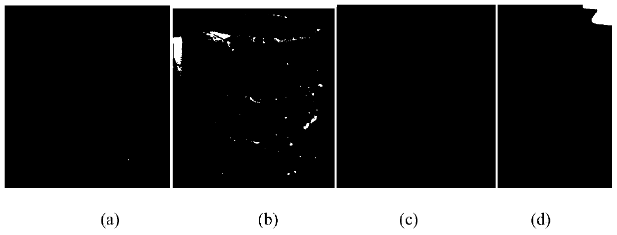
[0056] figure 1 It is a block diagram of the laser three-dimensional forming process detection system of the present invention, figure 2 It is a common defect diagram of laser stereoforming in the embodiment of the present invention.

[0057] A laser three-dimensional forming process detection method is characterized in that it comprises the following steps:

[0058] Step 1: Obtain the process parameter data of each equipment operating state through the equipment operating state detection device, and obtain the three-dimensional appearance of the part or the current layer or the molten pool area and its vicinity during the laser three-dimensional forming process through the structured light three-dimensional shape detection device 3 The surface topography data of the thermal component, the molten pool data in the image form of the molten pool shape, plume and splash during the laser three-dimensional forming process are obtained through the CCD molten pool detection device 1...

Embodiment 2

[0072] Such as figure 1 Shown:

[0073] A system for realizing a laser stereoforming process detection method,

[0074] Including multi-source heterogeneous information real-time monitoring device during forming process, data fusion evaluation model 4, data management system 5,

[0075]The multi-source heterogeneous information real-time monitoring device in the forming process includes: equipment operation state detection device, structured light three-dimensional shape detection device 3, CCD molten pool detection device 1, pyrometer temperature detection device 2; equipment operation state monitoring device: To obtain the process parameter data of each equipment operating state; the structured light three-dimensional shape detection device 3: used to obtain the thermal component surface of the three-dimensional shape of the part or the current layer or the molten pool area and its vicinity in the laser stereoforming process Shape data, structured light three-dimensional s...

Embodiment 3

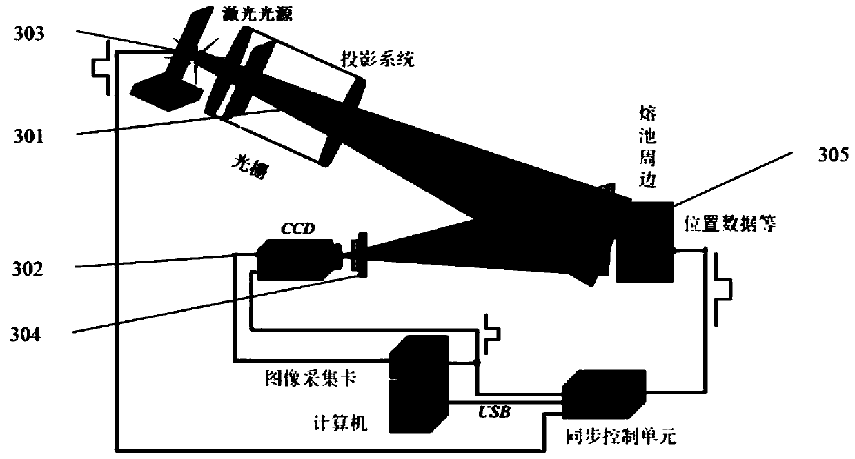
[0099] figure 2 is a common defect map of laser stereoforming in the embodiment of the present invention, image 3 It is a schematic diagram of the principle of measuring the molten pool and its vicinity by structured light in the present invention.

[0100] On the basis of Example 2, the structured light three-dimensional shape detection device 3 can figure 2 The topographical defects shown enable measurement in a laser environment or on the surface of a hot object. For an example of a measurement principle, see image 3 shown. The structured light three-dimensional shape detection device 3 is to perform the three-dimensional shape of the grating projection in the state of laser light emission during the laser three-dimensional forming process or when the forming object is in a hot state and high temperature state or when the measured area is a mixture of solid and liquid states Imaging; the wavelength of the light source required for its projection is determined accord...


PUM

PropertyMeasurementUnit
wavelengthaaaaaaaaaa

Abstract

The invention belongs to the field of additive manufacturing process detection and particularly relates to a laser three-dimensional forming process detecting system and method. A CCD molten pool detecting device, a pyrometer temperature detecting device, a structured light three-dimensional morphology detecting device, a data fusion evaluation model, a data management system and the like are mainly involved. The CCD molten pool detecting device is used for acquiring data for the molten pool state, plume and splash; the pyrometer temperature detecting device is used for acquiring molten pool center point average temperatures; the structured light three-dimensional morphology detecting device is used for acquiring data of three-dimensional morphologies of parts or the current layer or the area of and near a molten pool in the forming process; the data fusion evaluation model is used for performing fusion analysis and mutual comparative evaluation on the current data and obtaining fusioncharacteristic data; and the data management system is used for acquiring all process data including detecting data, forming process speed data, material data, motion coordinate data and the like, storing and managing the data according to a relation model, and pushing optimum process parameters according to the real-time state.

Description

technical field [0001] The invention relates to the field of intelligent manufacturing, in particular to a detection method, system and application of a laser three-dimensional forming process. Background technique [0002] Laser three-dimensional forming technology is one of the additive manufacturing technologies, and it is also the only additive manufacturing technology in which the mechanical properties of direct manufacturing can be equivalent to the level of castings or forgings of metal materials. Its essence is to apply the principle of rapid prototyping Laser three-dimensional forming technology combined with synchronous powder feeding laser cladding technology. Due to different naming rules, it is also referred to as LMD process, LMDF process, LENS process or LSF process. At present, the main purpose of additive manufacturing technology based on this process is to solve the manufacturing of complex structural parts, improve the ultimate performance of products, an...

Claims


Application Information

Patent Timeline
Patent Type & Authority Applications(China)
IPC IPC(8): B22F3/105B33Y40/00B33Y50/00
CPCB33Y50/00B33Y40/00B22F10/00B22F10/85B22F12/90B22F10/25B22F10/80Y02P10/25
Inventor 王敏刘广志张震陈波张馨月郎军
Owner 中国兵器装备集团自动化研究所有限公司
Learn More