Adjustable shielding device and electroplating shielding method implemented thereby
A shielding device and adjustable technology, which is applied in the direction of current insulation devices, circuits, electrolytic components, etc., can solve the problems that the uniformity of the coating thickness of the entire wafer cannot be guaranteed, and achieve the effect of wide versatility and uniformity
- Summary
- Abstract
- Description
- Claims
- Application Information
AI Technical Summary
Problems solved by technology
Method used
Image

Examples
Embodiment 1
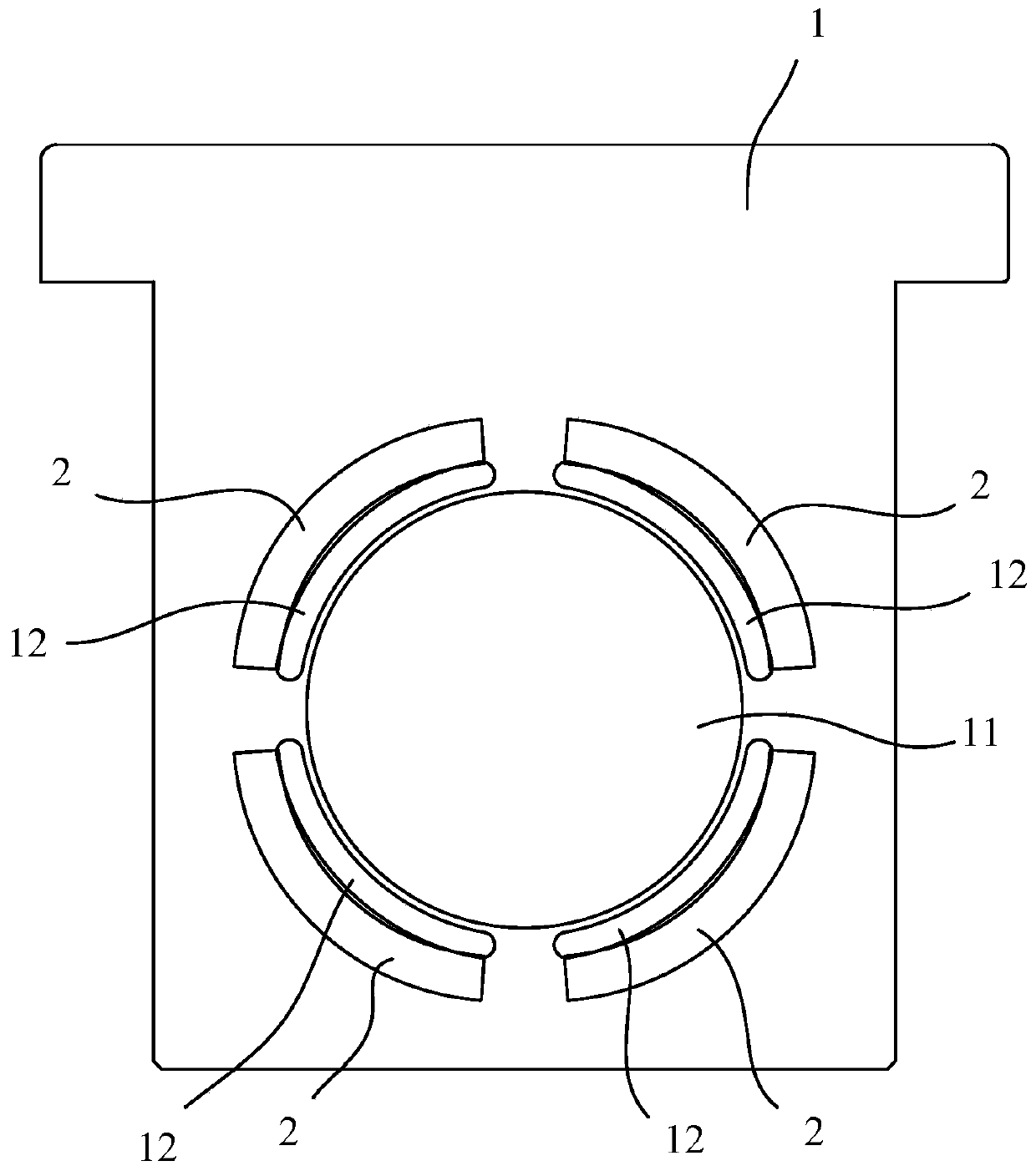
[0050] Such as figure 1 As shown, this embodiment discloses an adjustable shielding device, which includes a shielding plate 1 and four shielding plates 2 .
[0051] The shielding plate 1 is a structure with a hollow in the middle. Wherein, the shielding plate 1 has a hollow center portion 11 and several hollow arc portions 12 , and the arc portions 12 are arranged on the periphery of the center portion 11 .
[0052] The shielding plate 2 corresponds to each arc portion 12 respectively, and the shielding plate 2 moves relative to the arc portion 12 to adjust the covering area of the arc portion 12 .
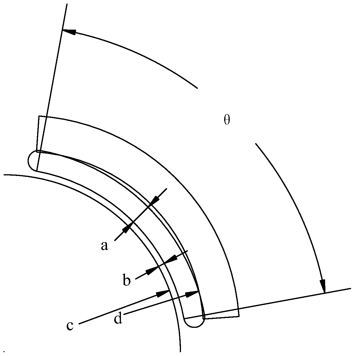
[0053] Such as figure 2 As shown, the arc portion 12 in this embodiment is arranged at a 45-degree diagonal angle of the shielding plate 1 . The angle θ corresponding to the arc portion 12 is 45-90 degrees, the hole width a is 10-20 mm, and the distance b between the arc portion 12 and the center portion 11 is 3-10 mm. Further preferably, the angle θ corresponding to the arc...
Embodiment 2
[0062] Such as Figure 4 As shown, this embodiment discloses an adjustable shielding device, which includes a shielding plate 1 and four shielding plates 2 .
[0063] The shielding plate 1 is a structure with a hollow in the middle. Wherein, the shielding plate 1 has a hollow center portion 11 and several hollow arc portions 12 , and the arc portions 12 are arranged on the periphery of the center portion 11 .
[0064] The shielding plate 2 corresponds to each arc portion 12 respectively, and the shielding plate 2 moves relative to the arc portion 12 to adjust the covering area of the arc portion 12 .
[0065] In this embodiment, the adjustable shielding device further includes a plurality of lever arms 3, and the lever arms 3 serve as adjustment mechanisms to drive each shielding plate 2 to move relative to the arc portion 12, thereby adjusting the covering area of the arc portion 12. Wherein, except the lever arm 3 of this embodiment, the adjustment mechanism may be any...
Embodiment 3
[0071] Such as Figure 5 and Figure 6 As shown, this embodiment discloses an adjustable shielding device, which includes a shielding plate 1 and four shielding plates 2 .
[0072] The shielding plate 1 is a structure with a hollow in the middle. Wherein, the shielding plate 1 has a hollow center portion 11 and several hollow arc portions 12 , and the arc portions 12 are arranged on the periphery of the center portion 11 .
[0073] The shielding plate 2 corresponds to each arc portion 12 respectively, and the shielding plate 2 moves relative to the arc portion 12 to adjust the covering area of the arc portion 12 .
[0074] Such as Figure 5 and Figure 6 As shown, the adjustable shielding device further includes a plurality of lever arms 3, which serve as adjustment mechanisms to drive each shielding plate 2 to move relative to the arc portion 12, thereby adjusting the covering area of the arc portion 12. Wherein, except the lever arm 3 of this embodiment, the adjustm...
PUM
 Abstract
Description
Claims
Application Information
 - Generate Ideas
- Intellectual Property
- Life Sciences
- Materials
- Tech Scout
- Unparalleled Data Quality
- Higher Quality Content
- 60% Fewer Hallucinations
Browse by: Latest US Patents, China's latest patents, Technical Efficacy Thesaurus, Application Domain, Technology Topic, Popular Technical Reports.
© 2025 PatSnap. All rights reserved.Legal|Privacy policy|Modern Slavery Act Transparency Statement|Sitemap|About US| Contact US: help@patsnap.com