Eureka AIR delivers breakthrough ideas for toughest innovation challenges, trusted by R&D personnel around the world.

Mechanical arm of earth auger

A technology of a mechanical arm and a digging machine, which is applied in the fields of electric machinery and digging machines, can solve the problems of high digging cost, high labor intensity, and low excavation rate, and achieve the effect of enhancing the digging effect and enhancing the excavation efficiency

Pending Publication Date: 2019-12-24
GUIGANG POWER SUPPLY BUREAU OF GUANGXI POWER GRID CO LTD
View PDF0 Cites 0 Cited by
  • Summary
  • Abstract
  • Description
  • Claims
  • Application Information

AI Technical Summary

Problems solved by technology

[0002] At present, when the poles of power supply lines are operated on the poles, they are generally constructed manually or with the cooperation of cranes and manual construction. The labor intensity is high and the cost of digging holes is high. Later, digging machines appeared to solve the above problems.
[0003] However, the mechanical arms of the digging machines for power grid towers in the prior art all use helical blades. The defects of the mechanical arms of this digging machine are: the diameter cannot be changed, different pit diameters must be equipped with drill bits of different diameters, and the excavation rate Low

Method used


Image

  • Mechanical arm of earth auger
  • Mechanical arm of earth auger
  • Mechanical arm of earth auger

Examples


Embodiment Construction

[0025] The following will clearly and completely describe the technical solutions in the embodiments of the present invention with reference to the accompanying drawings in the embodiments of the present invention. Obviously, the described embodiments are only some, not all, embodiments of the present invention. Based on the embodiments of the present invention, all other embodiments obtained by persons of ordinary skill in the art without creative efforts fall within the protection scope of the present invention.

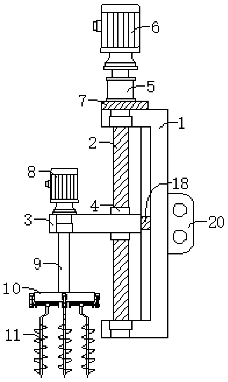
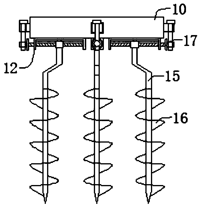
[0026] The present invention provides such Figure 1-3 The shown mechanical arm of a digging machine is composed of a lifting device and a variable diameter drill device.

[0027] The lifting device includes a U-shaped fixed plate 1, on which the first screw mandrel 2 is connected to the first screw mandrel bearing 21 and the second screw mandrel bearing 22 through transmission, and the first screw mandrel 2 passes through The screw nut is in transmission connecti...


PUM


Abstract

The invention aims to provide a mechanical arm of an earth auger. The mechanical arm comprises a lifting device and a variable-diameter drill bit device arranged on the lifting device, and is characterized in that the variable-diameter drill bit device comprises a disc, at least one variable-diameter drill bit is fixedly arranged at the bottom of the disc, and each variable-diameter drill bit comprises an inverted U-shaped fixing plate, a second lead screw in transmission connection with the inverted U-shaped fixing plate, a fixing mounting base in transmission connection with the second leadscrew, a expanding push rod fixedly arranged at the bottom of the fixing mounting base and a auger bit body fixedly connected to the expanding push rod. According to the mechanical arm, the problems that an existing earth auger for digging a pit for a power grid pole cannot change the diameter, drill bits with different diameters are required to be arranged for different pit diameters, and the pitdigging efficiency is low can be solved.

Description

technical field [0001] The invention belongs to the technical field of digging machines, in particular to a mechanical arm of a digging machine, and belongs to the field of electric machinery. Background technique [0002] At present, when the poles of power supply lines are operated on the poles, they are generally constructed manually or with the cooperation of cranes and manual labor. The labor intensity is high and the cost of digging holes is high. Then digging machines appeared to solve the above problems. [0003] However, the mechanical arms of the digging machines for power grid towers in the prior art all use helical blades. The defects of the mechanical arms of this digging machine are: the diameter cannot be changed, different pit diameters must be equipped with drill bits of different diameters, and the excavation rate Low. Contents of the invention [0004] The object of the present invention is to provide a variable-diameter drill bit to solve the problems ...

Claims


Application Information

Patent Timeline
IPC IPC(8): E02F5/20E02F5/16
CPCE02F5/20E02F5/16
Inventor 余弦李林穗陈世胜
Owner GUIGANG POWER SUPPLY BUREAU OF GUANGXI POWER GRID CO LTD
Why Eureka
Eureka Blog
Learn More