A non-porous disassembled aluminum formwork

An aluminum formwork, non-porous technology, used in formwork/formwork members, formwork/formwork/work frame connectors, on-site preparation of building components, etc., can solve the problem of adjusting the cavity size, flexibility and universality. Sexual problems, etc.

Active Publication Date: 2021-06-11
中铁一局集团建筑安装工程有限公司
View PDF7 Cites 0 Cited by
  • Summary
  • Abstract
  • Description
  • Claims
  • Application Information

AI Technical Summary

Problems solved by technology

However, the back flute fixing cavity of the existing non-porous formwork cannot adjust the size of the cavity according to the width and thickness of the back flute, and the flexibility and versatility are poor.

Method used


Image

  • A non-porous disassembled aluminum formwork
  • A non-porous disassembled aluminum formwork
  • A non-porous disassembled aluminum formwork

Examples


Embodiment 1

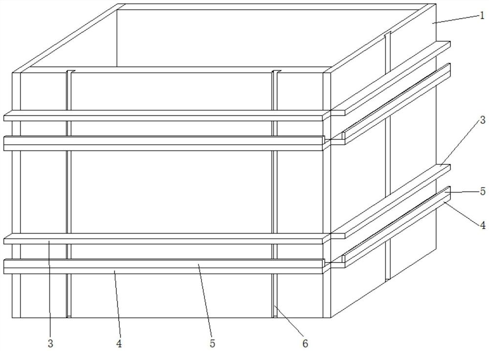
[0027] The invention provides a non-porous detachable aluminum formwork, specifically as Figure 1 to Figure 3 As shown, it includes formwork main body 1 and back flute 2, and an accommodating cavity for accommodating back flute 2 is arranged on the outside of formwork main body 1, and the accommodating cavity is composed of top plate 3, bottom plate 4 and baffle plate 5 arranged on bottom plate 4 The bottom plate 4 is fixedly connected with the formwork main body 1, the top plate 3 is slidably connected with the formwork main body 1 along the height direction of the formwork main body 1, a group of first through grooves 7 are arranged on the bottom plate 4 along the width direction, and the bottom of the baffle plate 5 is provided with connecting rods and Stopper, the upper end of the connecting rod is fixedly connected with the bottom of the baffle plate 5, the lower end of the connecting rod is fixedly connected with the stopper, the connecting rod passes through the first t...

Embodiment 2

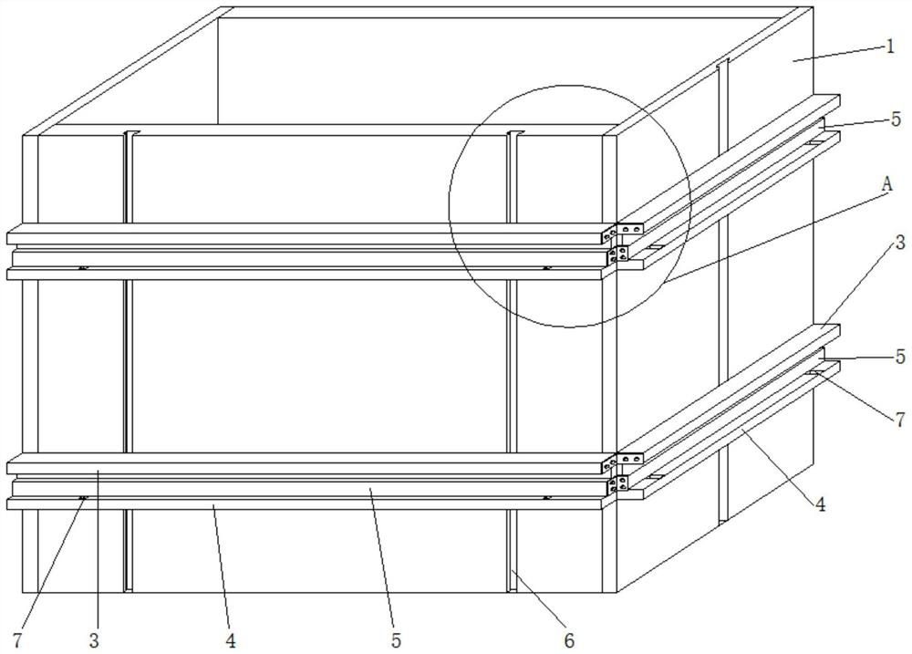
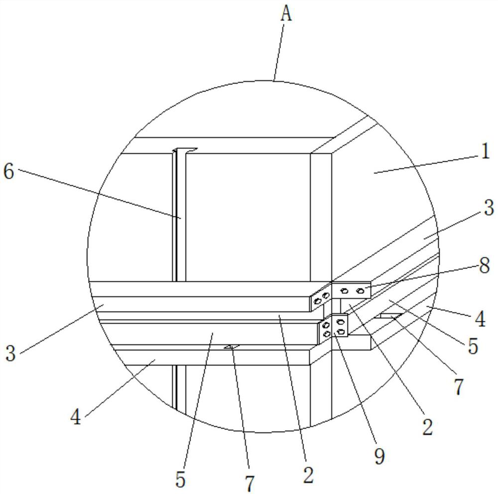
[0034] Such as Figures 4 to 6As shown, in this embodiment, the top plate 3 is provided with a second through groove 10 cooperating with the first through groove 7 along the width direction, and the second through groove 10 and the first through groove 7 are connected by fixing bolts 11, and the fixing bolts 11 The bottom is screwed with a limit nut. When this embodiment is in use, on the basis of connecting and fixing the adjacent two top plates 3 and the adjacent two baffle plates 5 through the first angle code 8 and the second angle code 9, the fixing bolt 11 is connected from the second through The groove 10 is passed through the first through groove 7, and the fixing bolt 11 is close to the baffle plate 5, and the limit nut is installed on the bottom of the bottom plate 4 to fasten it on the fixing bolt 11, so that the back flute 2 is more stable. Other structures are the same as those in Embodiment 1, and will not be repeated here.


PUM


Abstract

The invention provides a non-porous disassembled aluminum formwork, which belongs to the field of building formwork, and includes a formwork body and a back corrugation. An accommodating cavity for accommodating the back corrugation is provided on the outside of the formwork main body. The accommodating cavity consists of a top plate, The bottom plate is composed of a baffle plate arranged on the bottom plate, the bottom plate is fixedly connected with the formwork main body, the top plate is slidably connected with the formwork main body along the height direction of the formwork main body, a group of first through grooves are arranged on the bottom plate along the width direction, and a connecting rod is provided at the bottom of the baffle plate and the stopper, the upper end of the connecting rod is fixedly connected with the bottom of the baffle, the lower end of the connecting rod is fixedly connected with the stopper, the connecting rod passes through the first through groove, the stopper is arranged at the bottom of the bottom plate, and the back groove is arranged in the accommodating cavity, adjacent The top panels or baffles of the two formwork bodies are connected by fasteners. The aluminum formwork can be installed with different types of back flutes in a non-porous manner according to needs, to meet the support strength requirements, so that the structural performance of the poured concrete castings is better.

Description

technical field [0001] The invention belongs to the field of building templates, in particular to a non-porous disassembled aluminum template. Background technique [0002] The building formwork is a temporary support structure, which is manufactured according to the design requirements, so that the concrete structure and components are formed according to the specified position and geometric size, maintain their correct position, and bear the self-weight of the building formwork and the external load acting on it. The purpose of formwork engineering is to ensure the quality of concrete engineering and construction safety, speed up the construction progress and reduce engineering costs. [0003] At present, the commonly used formwork for concrete pouring in the construction industry includes steel formwork, wood formwork, plastic formwork, etc. Aluminum membrane panels are widely used due to their light weight, not easy to rust, easy to demould, good waterproof, and reusable...

Claims


Application Information

Patent Timeline
Patent Type & Authority Patents(China)
IPC IPC(8): E04G9/02E04G17/00
CPCE04G9/02E04G17/00
Inventor 陈鸿胡展孝白刚范洪涛赵盼
Owner 中铁一局集团建筑安装工程有限公司
Why Eureka
Try Eureka