Eureka AIR delivers breakthrough ideas for toughest innovation challenges, trusted by R&D personnel around the world.

Refrigeration bin and system of in-vitro diagnosis equipment

A technology for in vitro diagnosis and equipment, which is applied in the direction of refrigerators, refrigeration and liquefaction, household refrigeration devices, etc., and can solve the problems of limited internal space, high overall cost, and environmental pollution of in vitro diagnostic equipment.

Inactive Publication Date: 2019-12-24
东软威特曼生物科技(沈阳)有限公司
View PDF7 Cites 1 Cited by
  • Summary
  • Abstract
  • Description
  • Claims
  • Application Information

AI Technical Summary

Problems solved by technology

The direct-mounted structure installs the heat sink directly on the lower part or side of the reagent compartment, which has the following disadvantages: 1) Due to the limited internal space of the in vitro diagnostic equipment, it will cause difficulties in installation and maintenance; the use of hot air inside the in vitro diagnostic equipment (air temperature higher than room temperature ) does not have a good effect on Peltier heat dissipation and cooling, and it will also cause the internal temperature of the equipment to rise and accelerate the aging of the equipment
The water-cooled structure needs to be equipped with a water tank and a circulating pump. The water-cooled pipeline is complex and has many fault points. The water pump is prone to heat when it runs for a long time, which consumes a lot of energy and the overall cost is high. , due to the volatilization of the liquid, it often needs to be replenished regularly, such as the leakage of cooling fluid will cause environmental pollution
[0004] Therefore, there are still many technical defects in the refrigeration technology of existing in vitro diagnostic equipment, which needs to be improved urgently.

Method used


Image

  • Refrigeration bin and system of in-vitro diagnosis equipment
  • Refrigeration bin and system of in-vitro diagnosis equipment
  • Refrigeration bin and system of in-vitro diagnosis equipment

Examples


Embodiment Construction

[0020] Reference will now be made in detail to the exemplary embodiments, examples of which are illustrated in the accompanying drawings. When the following description refers to the accompanying drawings, the same numerals in different drawings refer to the same or similar elements unless otherwise indicated. Embodiments described in the following exemplary embodiments do not represent all embodiments consistent with the present application. Rather, they are merely examples of apparatuses and methods consistent with aspects of the present application as recited in the appended claims.

[0021] The terminology used in this application is for the purpose of describing particular embodiments only, and is not intended to limit the application. As used in this application and the appended claims, the singular forms "a", "the", and "the" are intended to include the plural forms as well, unless the context clearly dictates otherwise.

[0022] It should be understood that "first", ...


PUM


Abstract

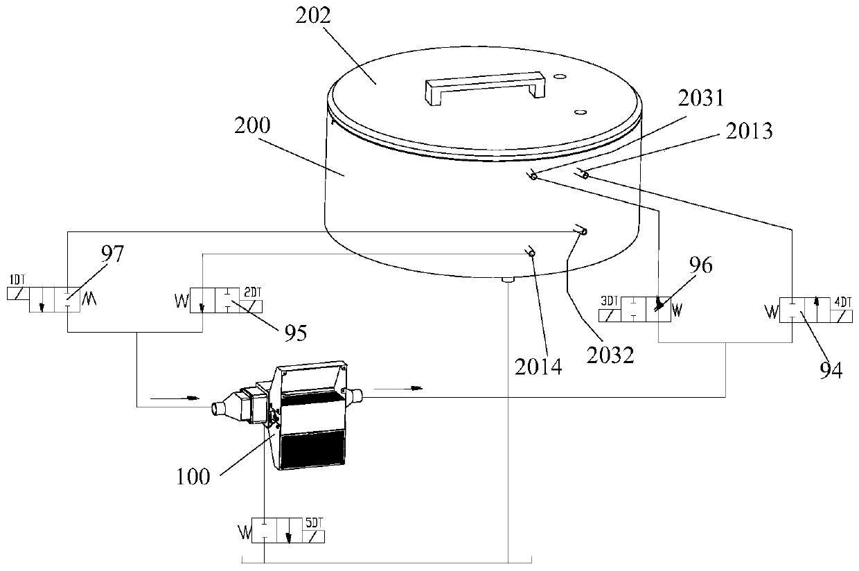
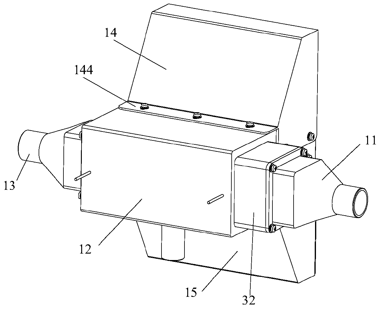
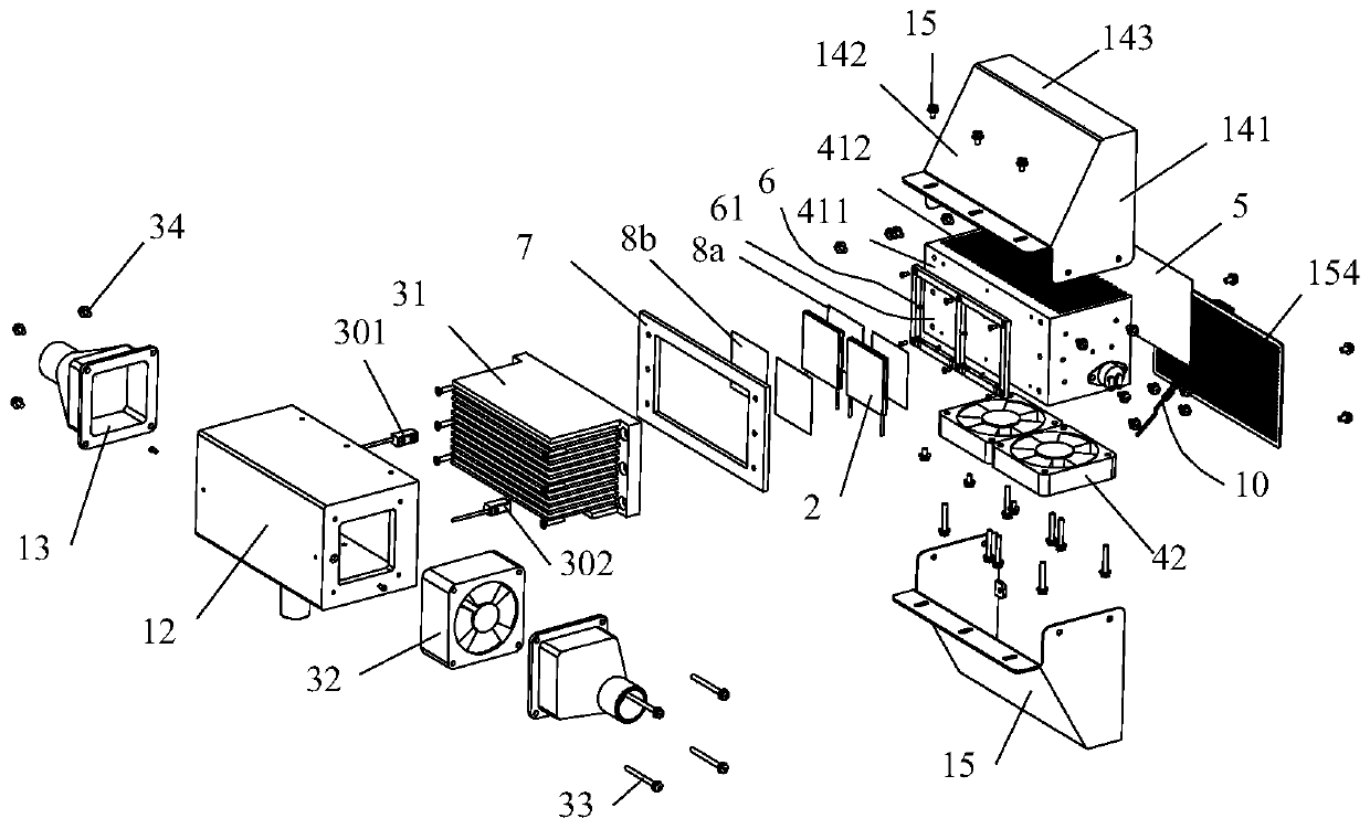
The invention discloses a refrigeration bin and system of in-vitro diagnosis equipment and a reagent bin. The refrigeration system comprises a controller, the refrigeration bin and the reagent bin. The refrigeration bin comprises a shell, a heat dissipation assembly, a cooling assembly and a Peltier. The heat dissipation assembly comprises a heat dissipation fan and a heat dissipation sheet, and the heat dissipation sheet absorbs heat of the Peltier; the heat dissipation fan blows air outside the refrigeration bin to the heat dissipation sheet and conducts heat exchange with the heat dissipation sheet, so that hot air is discharged to the exterior of the shell. The cooling assembly comprises a cooling sheet and a cooling fan. The reagent bin is connected with the refrigeration bin througha pipe and comprises a cold-temperature temperature sensor. The controller controls the cooling fan to rotate when a cold-end detection temperature value obtained by a cold-end temperature sensor is larger than a cold-end temperature threshold value, otherwise, the cooling fan is controlled to stop rotating and / or the Peltier is controlled to be powered off. Since the Peltier is arranged at the refrigeration bin, convenience is provided for design layout and installation maintenance, and the refrigeration bin and the refrigeration system are simple in structure.

Description

technical field [0001] The present application relates to the technical field of in vitro diagnostics, in particular to a refrigerating cabin of in vitro diagnostic equipment and a refrigerating system thereof. Background technique [0002] At present, in vitro diagnosis is one of the most commonly used diagnostic methods in the medical field. In vitro diagnosis is classified according to the detection principle or detection method, and is mainly divided into biochemical diagnosis, immune diagnosis, molecular diagnosis, microbial diagnosis, urine diagnosis, blood coagulation diagnosis, blood and Diagnostic methods such as flow cytometry diagnosis, among which biochemical diagnosis, immunodiagnosis and molecular diagnosis are the main methods of in vitro diagnosis in my country at present. These diagnostic methods all use fully automatic or semi-automatic instruments to add samples and analyze, and give diagnostic reports. When testing different items, corresponding reagents ...

Claims


Application Information

Patent Timeline
IPC IPC(8): F25D13/00F25D17/06F25B21/02
CPCF25B21/02F25D13/00F25D17/06
Inventor 刘春雨吴海波王丹民郭成哲
Owner 东软威特曼生物科技(沈阳)有限公司
Why Eureka
Eureka Blog
Learn More