
Free trajectory construction method for specifying launching elevation angle

A construction method and ballistic technology, applied in special data processing applications, complex mathematical operations, instruments, etc., can solve problems such as unspecified missile construction methods, unresolved ballistic construction methods, and inability to meet high-precision ballistic construction requirements, etc.

Active Publication Date: 2019-12-24
ZIJINSHAN ASTRONOMICAL OBSERVATORY CHINESE ACAD OF SCI
View PDF8 Cites 9 Cited by
  • Summary
  • Abstract
  • Description
  • Claims
  • Application Information

AI Technical Summary

Problems solved by technology

Method 1 does not give the missile construction method considering the perturbation force, nor does it solve the ballistic construction method when the launching point and the target point have different geocentric radial lengths, and cannot meet the requirements of high-precision ballistic construction

Method used


Image

  • Free trajectory construction method for specifying launching elevation angle
  • Free trajectory construction method for specifying launching elevation angle
  • Free trajectory construction method for specifying launching elevation angle

Examples


Embodiment 1

[0174] Example 1: Launch time t of any given missile 0 , the geodetic coordinates of launch point A and target point B (see Table 1 for specific parameters), respectively in the two-body motion model and considering the earth's gravity field J 2 All forward and reverse free trajectories are constructed traversally under the perturbed dynamic model.

[0175] Table 1 Example 1

[0176] (Launch time: 13:45:18.732 on August 24, 2012, Beijing time; launch elevation angle h: traversal)

[0177] dot Longitude L (degrees) Geodetic latitude B (degrees) Earth height H (m) A 86.384 -60.756 14.00 B 116.403 60.905 49.00

Embodiment 2

[0178] Example 2: Launch time t of any given missile 0 and the geodetic geographic coordinates of the target point B, the launch point A is located at the North Pole (see Table 2 for the specific parameters), respectively in the two-body motion model and considering the earth's gravity field J 2 All forward and reverse free trajectories are constructed traversally under the perturbed dynamic model.

[0179] Table 2. Example 2

[0180] (Launch time: 13:55:25.6, May 18, 2012, Beijing time; launch elevation angle h: traversal)

[0181]

[0182] Except above-mentioned known condition, the present invention has also used following geophysical constant: the equatorial radius a of reference ellipsoid e =6378136m; gravitational constant μ=0.39860043770442×10 15 m 3 / s 2 ;Earth flattening f=1 / 298.25781;Earth meridian eccentricity:

[0183] Analyzing the above conditions, the launch time and the geodetic coordinates of the launch point are known quantities, and the coordinate...


PUM


Abstract

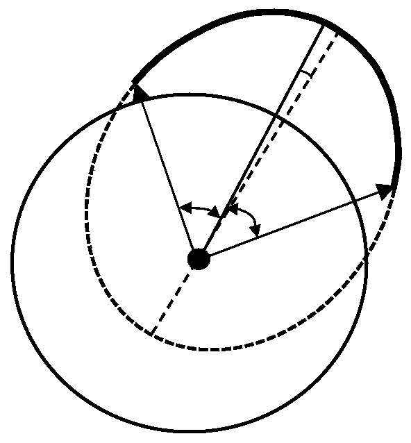
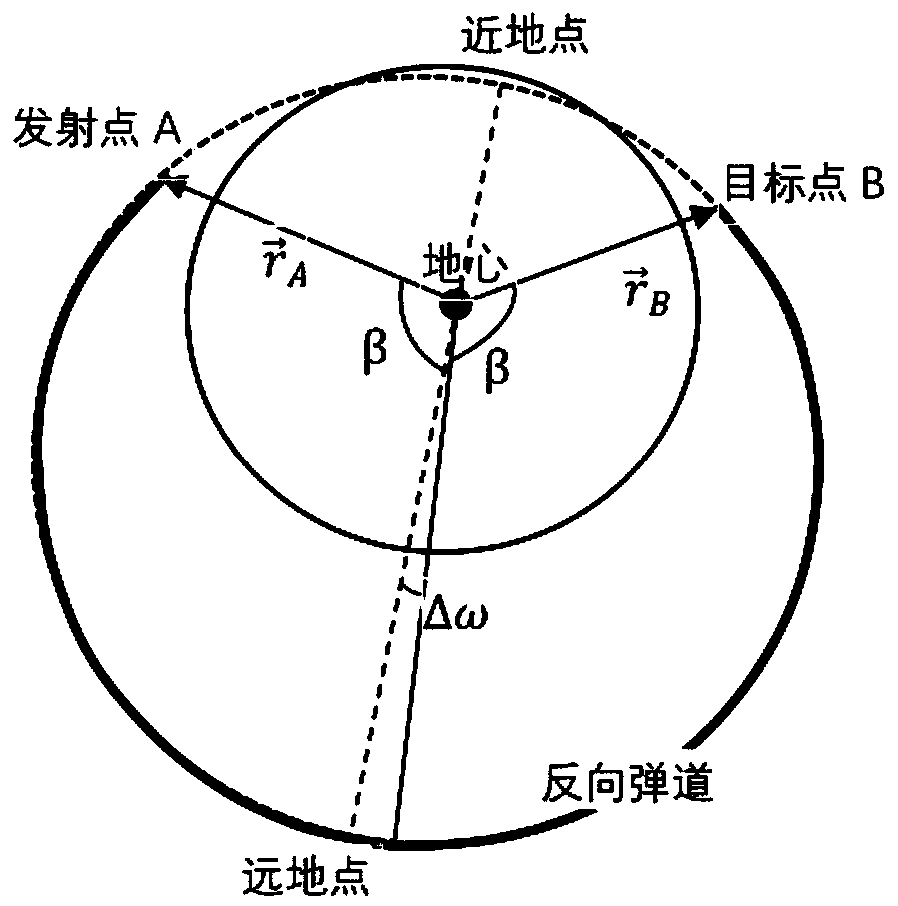
The invention discloses a free trajectory construction method with a specified launching elevation angle. The method comprises the steps of firstly, orderly calculating the earth-fixed rectangular coordinate vectors of a launching point and a target point, the difference between the earth latitude and the geocentric latitude, a horizontal included angle and the difference between the ratio of geocentric radial modes of the point A and the point B and 1; solving the variables, such as the launching speed of a forward trajectory or a reverse trajectory in an orbit coordinate system, the launching speed of the forward trajectory or the reverse trajectory in an earth-fixed coordinate system, the number sigma of trajectories / orbits, flight time and the like in the iterative initial state and the two-body motion model, wherein the newly solved flight time is T *; enabling T to be equal to T *, repeatedly iteratively calculating the launching speed of the missile and the like, ending iteration until the absolute value of (T-T *) is smaller than a set threshold St, finally obtaining the launching speed and flight time T of the missile under the two-body motion model, and outputting the design parameters vp, vr, T and sigma. According to the present invention, the forward trajectory and the reverse trajectory can be constructed at the specified launching elevation angles under a two-body motion model and a kinetic model considering the J2 perturbation of an earth gravitational field respectively, and then all trajectories from the launching points to the target points are obtained by traversing the launching elevation angles.

Description

technical field [0001] The invention belongs to the ballistic structure technology for solving ballistic missiles under the framework of celestial mechanics, in particular to a free ballistic structure method with a specified launching elevation angle. Background technique [0002] Ballistic structure is the basis of ballistic research and element design. The full ballistic is composed of active section, free flight section and reentry section. The full ballistic structure is usually based on the specific performance parameters of the missile. Its realization requires some difficult-to-know technical parameters and physical conditions, and the calculation process is complex and time-consuming, which cannot meet the general ballistic research and application requirements. In contrast, the free-flight segment, which occupies most of the entire trajectory, is simple in force, mainly due to the gravitational force of the earth on the center of mass of the missile body, and the d...

Claims


Application Information

Patent Timeline
IPC IPC(8): G06F17/10G06F17/11G06F17/16
CPCG06F17/10G06F17/11G06F17/16G06F17/13G06F30/20G06F2119/14G06F2111/10
Inventor 徐劲马剑波杜建丽曹志斌杨冬
Owner ZIJINSHAN ASTRONOMICAL OBSERVATORY CHINESE ACAD OF SCI
Learn More