
Full-automatic butting device for reinforcement cage in municipal construction engineering

A fully automatic technology for construction engineering and cages, applied in the field of construction engineering, can solve the problems of time-consuming and laborious, poor standardization, etc., and achieve the effects of various types of applications, reduced workload, and convenient use.

Inactive Publication Date: 2019-12-27
吴晓建
View PDF4 Cites 1 Cited by
  • Summary
  • Abstract
  • Description
  • Claims
  • Application Information

AI Technical Summary

Problems solved by technology

[0002] In the rapid development of civil construction projects, it is necessary to introduce advanced technical means to reduce labor costs and construction quality. The connection of steel bars in construction is the most basic and important part. In the process, the most basic manual labor is often required. When the reinforcement cage is tied, the main reinforcement needs to be manually supported. Because the reinforcement is very heavy, it is often bent or tilted. In addition, due to the different thickness of the reinforcement cage, sometimes the shape It is also undecided, and the moving supports need to be placed manually, which is time-consuming and labor-intensive, and the standardization is poor

Method used


Image

  • Full-automatic butting device for reinforcement cage in municipal construction engineering
  • Full-automatic butting device for reinforcement cage in municipal construction engineering
  • Full-automatic butting device for reinforcement cage in municipal construction engineering

Examples


Embodiment 1

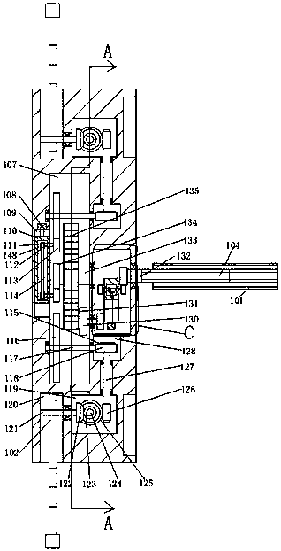
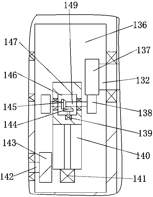
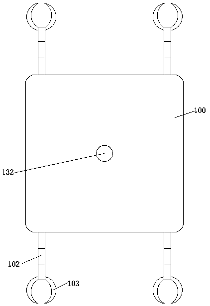
[0028] see Figure 1-9 , a fully automatic tie-joining device for reinforcement cages in municipal construction projects, which includes an annular housing 150 and a main reinforcement supporting body 100, the annular housing 150 and the main reinforcement supporting body 100 are two completely separated parts, and the annular housing 150 is provided with An annular cavity 159, the annular housing 150 is provided with a plurality of butt holes 151 distributed in the circumferential direction through the annular cavity 159, and the inner wall of the inner ring of the annular housing 150 is provided with a hole between any two adjacent butt holes 151. The double-layer first slot 161, the device also includes a cylindrical shell 167 located at the center of the annular housing 150 with an upward opening, and the inner wall of the side of the cylindrical shell 167 is provided with a second slot corresponding to the first slot 161 one-to-one. 179, the side surface of the shell 167 ...


PUM


Abstract

The invention relates to a full-automatic butting device for a reinforcement cage in municipal construction engineering. The full-automatic butting device comprises an annular shell and a main reinforcement support main body, wherein the annular shell and the main reinforcement support main body are two parts which are completely separated, an annular cavity is formed in the annular shell, the annular shell penetrates through the annular cavity and is provided with a plurality of butting holes distributed in the circumferential direction, and the inner wall of an inner ring of the annular shell is provided with first inserting grooves which are located between any two adjacent butting holes in a penetrating manner. The device further comprises a cylindrical shell with an upward opening located in the center of the annular shell, second inserting grooves which are in one-to-one correspondence with the first inserting grooves are arranged in the inner wall of the side surface of the cylindrical shell in a penetrating manner, and the side surface of the cylindrical shell is located on the end surface between every two adjacent second inserting grooves and is fixedly connected with a double-layer fixing rod which is distributed back and forth between the side surfaces of the inner wall of the annular shell between every two adjacent first inserting grooves.

Description

technical field [0001] The invention relates to the technical field of construction engineering, in particular to a fully automatic binding device for reinforcement cages in municipal construction engineering. Background technique [0002] In the rapid development of civil construction projects, it is necessary to introduce advanced technical means to reduce labor costs and construction quality. The connection of steel bars in construction is the most basic and important part. In the process, the most basic manual labor is often required. When the reinforcement cage is tied, the main reinforcement needs to be manually supported. Because the reinforcement is very heavy, it is often bent or tilted. In addition, due to the different thickness of the reinforcement cage, sometimes the shape It is also undecided, and the moving supports need to be placed manually, which is time-consuming and labor-intensive, and the standardization is poor. Contents of the invention [0003] 1....

Claims


Application Information

Patent Timeline
IPC IPC(8): B21F27/20
CPCB21F27/20
Inventor 吴晓建
Owner 吴晓建
Learn More