Cooling liquid flow monitoring method and liquid cooling electric drive system

A flow monitoring and cooling liquid technology, which is applied in liquid/fluid solid measurement, measuring flow/mass flow, electrical devices, etc., can solve the problem that the cooling liquid flow cannot be monitored, achieve high reliability, avoid dispersion, and improve Product Cost Effects

Active Publication Date: 2019-12-27
UNITED AUTOMOTIVE ELECTRONICS SYST
View PDF10 Cites 3 Cited by
  • Summary
  • Abstract
  • Description
  • Claims
  • Application Information

AI Technical Summary

Problems solved by technology

[0003] The purpose of the present invention is to provide a coolant flow monitoring method and a liquid-cooled electric drive system to solve the problem that the coolant flow cannot be monitored in the existing electric drive system

Method used


Image

  • Cooling liquid flow monitoring method and liquid cooling electric drive system
  • Cooling liquid flow monitoring method and liquid cooling electric drive system
  • Cooling liquid flow monitoring method and liquid cooling electric drive system

Examples


Embodiment 1

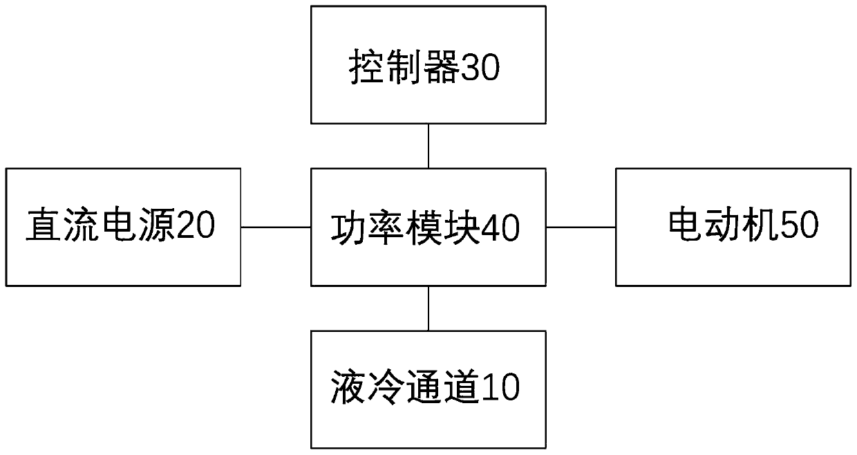
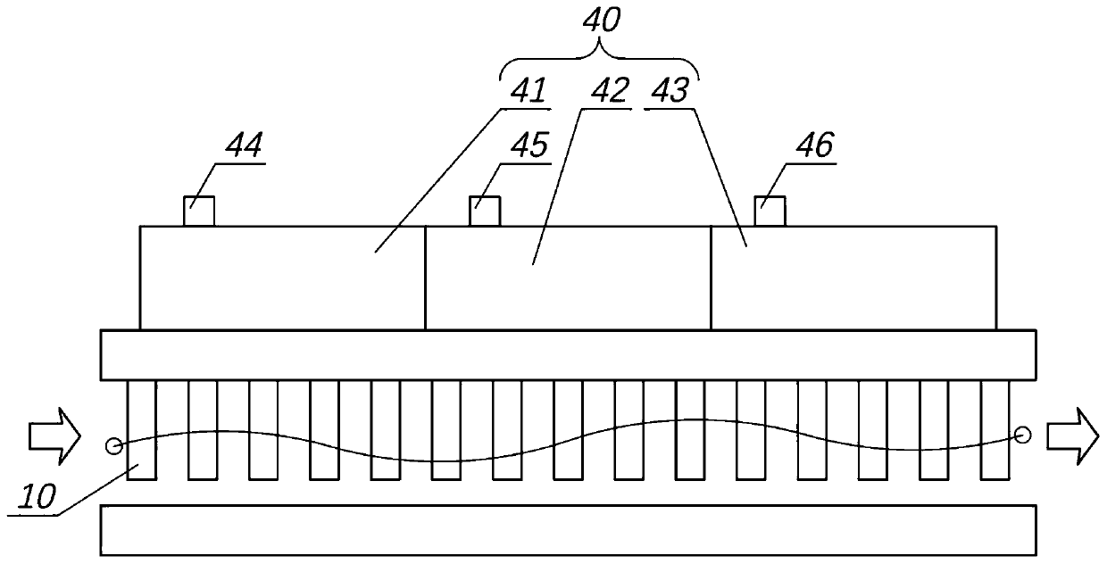
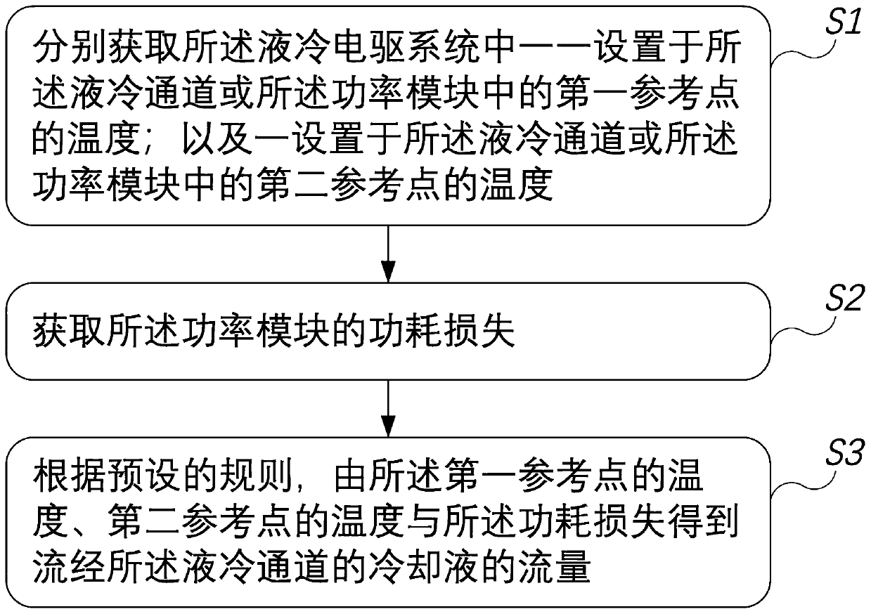
[0072] Please refer to Figure 1 to Figure 4 ,in, figure 1 It is a schematic diagram of the liquid-cooled electric drive system provided in Embodiment 1 of the present invention, figure 2 It is a schematic diagram of the power module and the liquid cooling channel provided by Embodiment 1 of the present invention, image 3 It is a flow chart of the coolant flow monitoring method provided in Embodiment 1 of the present invention, Figure 4 It is a flow chart of preset rules of the coolant flow monitoring method provided in Embodiment 1 of the present invention.

[0073] Embodiment 1 of the present invention provides a coolant flow monitoring method and a liquid-cooled electric drive system. The coolant flow monitoring method is mainly used in liquid-cooled electric drive systems, such as figure 1 As shown, in an exemplary embodiment, the liquid-cooled electric drive system includes a liquid-cooled channel 10, a DC power supply 20, a control module 30, a power module 40, and...

Embodiment 2

[0090] The cooling liquid flow monitoring method and the liquid-cooled electric drive system of the second embodiment of the present invention are basically the same as those of the first embodiment, the same parts will not be described, and only the differences will be described below.

[0091] Please refer to Figure 5 , which is a flow chart of preset rules of the coolant flow monitoring method provided in Embodiment 2 of the present invention.

[0092] In the second embodiment, the setting positions of the first reference point and the second reference point are different from those in the first embodiment. Specifically, the first reference point is set in the liquid cooling channel 10, and the second reference point is set in the power module 40, such as Figure 5 As shown, the preset rules specifically include:

[0093] Step S32a: using the temperature difference measured between the first reference point and the second reference point as the second temperature differe...

Embodiment 3

[0109] In the third embodiment, both the first reference point and the second reference point are set in the power module 40. Preferably, the power module 40 includes a multi-phase power unit, and the multi-phase power unit Arranged in sequence according to the flow direction of the coolant, the first reference point is set on the power unit close to the inlet of the coolant, and the second reference point is set on the power unit close to the outlet of the coolant superior. In an exemplary embodiment, the liquid-cooled electric drive system includes a first temperature sensor and a second temperature sensor, please refer to figure 2 , the three-phase power units 41, 42, 43 of the power module 40 are arranged sequentially along the flow direction of the coolant, the NTC temperature sensor 44 is configured as a first temperature sensor, and is set as a first reference point, and the NTC temperature sensor 46 Configured as the first temperature sensor and set as the second ref...


PUM


Abstract

The invention provides a cooling liquid flow monitoring method and a liquid cooling electric drive system. By obtaining the temperatures of the two reference points in the liquid cooling electric drive system and the power consumption loss of a power module, the flow of the cooling liquid flowing through the power module can be obtained, and the problems that an existing vehicle provided with theelectric drive system cannot obtain the actual flow of the cooling liquid and is prone to cooling abnormity, and consequently the system faults are caused, are solved. Furthermore, by calculating thetemperature detection values of the two reference points in the liquid cooling electric drive system and the power consumption loss of the power module, the physical sensors, such as a flow sensor, etc., do not need to be additionally arranged on the liquid cooling electric drive system, the product cost is not increased, the problems caused by scattering difference and faults of the physical sensors are also avoided, and the reliability is high.

Description

technical field [0001] The invention relates to the technical field of new energy vehicles, in particular to a coolant flow monitoring method and a liquid-cooled electric drive system. Background technique [0002] The cooling system in the electric drive system of new energy vehicles is responsible for cooling the power components such as batteries, inverters, and motors. However, once the cooling system fails and the high power output is still performed, the power device will be overheated and damaged, causing unexpected power loss and affecting vehicle and personal safety. At present, the cooling system used for the electric drive system on the vehicle generally uses a PWM water pump or a switch water pump to control the flow of coolant. Most of them do not have a flow sensor for measurement and adopt open-loop control. Once the coolant leakage, blockage, etc. are often not easy to find, and at this time, if the inverter, motor and other power devices output high power, ...

Claims


Application Information

Patent Timeline
Patent Type & Authority Applications(China)
IPC IPC(8): B60L3/00G01F1/69
CPCB60L3/00G01F1/69
Inventor 黄宜坤
Owner UNITED AUTOMOTIVE ELECTRONICS SYST
Why Eureka
Try Eureka