Rectangular liquid tank sloshing damping device and rectangular liquid tank hydrodynamic calculation method

A liquid tank sloshing and damping device technology, applied in calculation, transportation and packaging, for bulk cargo, etc., can solve the problems of reducing water body exchange and effective volume, local horizontal solid plates cannot provide sloshing damping, etc., to ensure Effects of rigor and validity

Inactive Publication Date: 2019-12-27
NINGBO INST OF TECH ZHEJIANG UNIV ZHEJIANG
View PDF8 Cites 7 Cited by
  • Summary
  • Abstract
  • Description
  • Claims
  • Application Information

AI Technical Summary

Problems solved by technology

[0005] The present invention reduces the water body exchange and effective volume in the rectangular liquid tank for vertical partitions and horizontal partitions that completely cover the water surface, but a single partial horizontal solid plate cannot provide sufficient sloshing damping and other technical problems

Method used


Image

  • Rectangular liquid tank sloshing damping device and rectangular liquid tank hydrodynamic calculation method
  • Rectangular liquid tank sloshing damping device and rectangular liquid tank hydrodynamic calculation method
  • Rectangular liquid tank sloshing damping device and rectangular liquid tank hydrodynamic calculation method

Examples


example 1

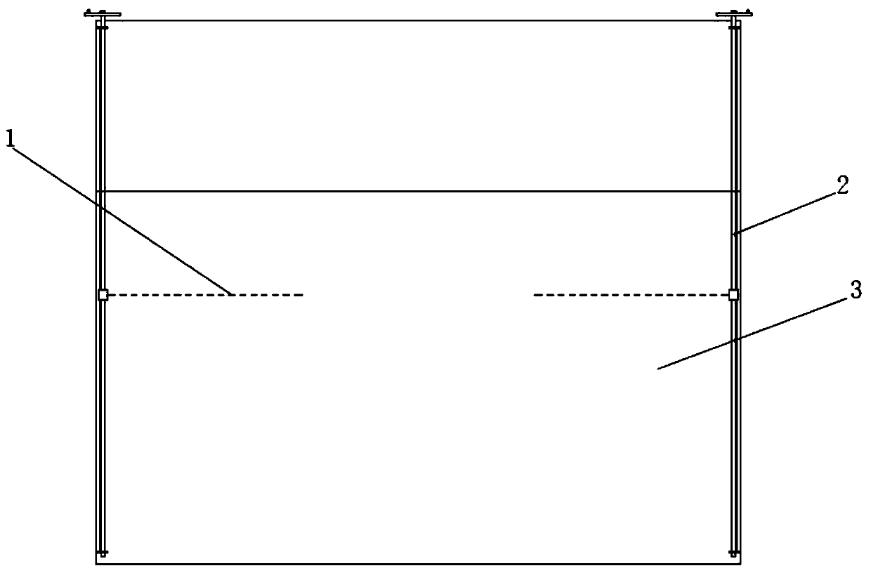
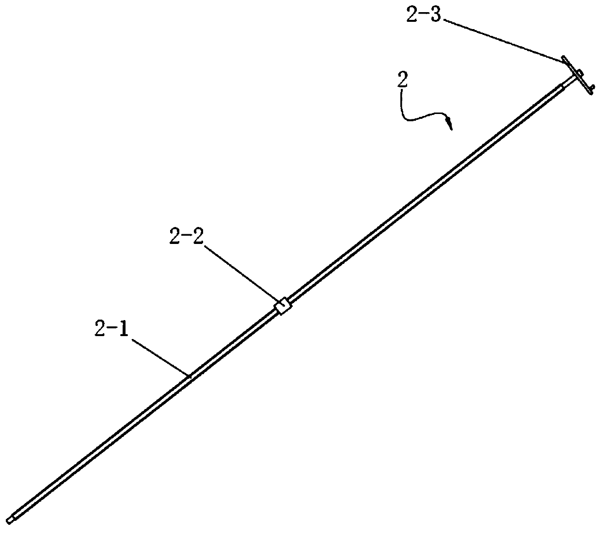
[0050] Such as figure 1 As shown, a rectangular liquid tank sloshing damping device includes a pair of symmetrically distributed horizontal partitions 1 separated by a certain distance; a pair of horizontal partitions 1 are installed to the corresponding on the inner wall of the liquid tank 3, and adjust the position in the height direction of the liquid tank 3 through the screw slider mechanism 2; as figure 2 As shown, the screw slider mechanism 2 includes a screw 2-1 extending along the height direction of the tank 3, a slider 2-2 reciprocating along the screw 2-1 and a hand wheel 2-3 , wherein, a threaded rod 2-1 is fixed to the inner wall of the liquid tank 3 through a pair of mounts, one side of the rod end extends from the top opening of the liquid tank 3 to the outside of the liquid tank 3, and a hand wheel 2-3 is installed To the end of the side rod, by adjusting the hand wheel 2-3, the slider 2-2 can be conveniently driven to move and position along the axial direct...


PUM


Abstract

The invention discloses a liquid tank sloshing damping device, and particularly relates to a rectangular liquid tank sloshing damping device which comprises a pair of symmetrically distributed horizontal perforated partition plates. A certain distance is reserved between the pair of symmetrically distributed horizontal perforated partition plates, the pair of horizontal partition plates is mountedon the inner side walls of the liquid tank corresponding to the horizontal partition plates through the lead screw sliding block mechanisms, and the positions of the horizontal partition plates are adjusted in the height direction of the liquid tank through the lead screw sliding block mechanisms. Meanwhile, the invention further provides a corresponding rectangular liquid tank hydrodynamic calculation method with a local horizontal perforated plate. The horizontal perforated plate damping device provided by the invention can provide the additional damping when a water body in a cabin sloshes, achieves the technical purpose of reducing the liquid sloshing phenomenon of the rectangular liquid tank, and has a rectangular liquid tank sloshing inhibition effect, and the hydrodynamic calculation method can directly consider the influence of the length, height and porosity of the horizontal perforated plate on the water body sloshing under the specified liquid tank movement displacement andperiod, a calculation and analysis result and a physical model test result are in good conformity, and the reference can be provided for the design of the liquid tank damping device.

Description

technical field [0001] The invention relates to a sloshing damping device for a liquid tank, in particular to a sloshing damping device for a rectangular liquid tank, and also provides a hydrodynamic calculation method for a rectangular liquid tank. Background technique [0002] Most of the existing sloshing damping devices or technologies rely on sloshing partitions to suppress sloshing in tanks. From the perspective of partition layout, it is mainly divided into vertical layout and horizontal layout. For the sloshing damping device arranged vertically, it has a good sloshing effect, but the sloshing effect of the vertical partition is positively correlated with the plate height, in order to achieve a good sloshing effect, the top of the partition must be infinitely close to or exceed the free liquid surface, resulting in The liquid tank is divided into multiple subspaces, which reduces the effective volume of the liquid tank. For horizontally arranged partitions, in orde...

Claims


Application Information

Patent Timeline
Patent Type & Authority Applications(China)
IPC IPC(8): B63B25/12B63B11/00G06F17/50
CPCB63B11/00B63B25/12
Inventor 金恒宋瑞银刘帅敏陈凯翔
Owner NINGBO INST OF TECH ZHEJIANG UNIV ZHEJIANG
Why Eureka
Try Eureka