Pipeline conveying device in limited work space

A work space and conveying device technology, applied in conveyors, conveyor objects, transportation and packaging, etc., can solve problems such as affecting road traffic, unfavorable resource optimal allocation, dust pollution, etc., and achieve the effect of reducing manpower

Pending Publication Date: 2019-12-27
HEBEI SCI & ENG CONSTR ENG GRP CO LTD
View PDF0 Cites 5 Cited by
  • Summary
  • Abstract
  • Description
  • Claims
  • Application Information

AI Technical Summary

Problems solved by technology

This traditional operation method has many disadvantages. It not only requires a lot of manpower and material resources to operate at the same time, which is not conducive to the optimal allocation of resources; moreover, the road surface where the entire pipeline is located needs to be removed, and large-scale earthwork operations will affect road traffic. Cause dust to pollute the environment

Method used


Image

  • Pipeline conveying device in limited work space
  • Pipeline conveying device in limited work space
  • Pipeline conveying device in limited work space

Examples


Embodiment Construction

[0026] Preferred embodiments of the present invention will be described below in conjunction with the accompanying drawings. It should be understood that the preferred embodiments described here are only used to illustrate and explain the present invention, not to limit the present invention.

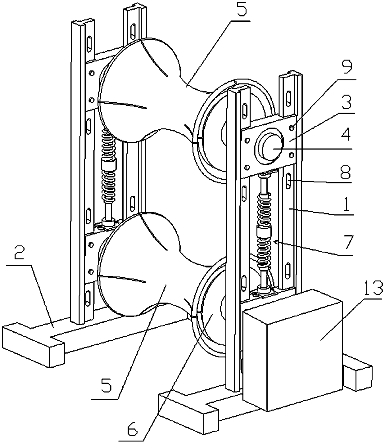
[0027] The invention discloses a pipeline conveying device in a limited working space, such as figure 1 Shown, base 2, frame 1 and two conveying rollers, wherein, frame 1 is vertically installed on the base 2, and two conveying rollers are installed on the frame 1 movablely at intervals along the vertical direction, each conveying roller The outer peripheral surface is a concave arc surface, and the two axial ends of each conveying roller are respectively movably connected with a curvature adjusting mechanism 6 which can change the curvature of the arc surface, and an elastic tightening mechanism 7 is arranged between the two conveying rollers , and at least one of the two conveying ro...


PUM


Abstract

The invention discloses a pipeline conveying device in limited work space. The device comprises a rack vertically mounted on a base, two conveying rollers are movably connected to the rack in a spacedmanner in the vertical direction of the rack, the periphery faces of the conveying rollers are inwards-concave arc faces, the two axial ends of the conveying rollers are movably connected with curvature adjusting mechanisms capable of changing the arc face curvature, an elastic tightening mechanism is arranged between the two conveying rollers, at least one in the two conveying rollers is drivenby a driving mechanism to roll, and conveying of a pipeline which is clamped between the two conveying rollers and is matched with the arc faces of the two conveying rollers can be achieved. The device has the advantages that manpower and material resources are saved, the road face where the whole pipeline to be replaces is located does not need to be broken down, and in the operation process, raised dust is avoided; and the device is suitable for replacing of the pipeline laid in the limited work space of a trench.

Description

technical field [0001] The invention belongs to the technical field of replacement of pipelines laid in trenches, and in particular relates to a pipeline conveying device in a limited working space. Background technique [0002] For the steam pipeline laid in the trench, when replacing it with a high-temperature water pipeline, the traditional method is: pavement removal→earth excavation→lifting the trench cover→removing the original steam insulation pipe and bracket→laying sand cushion→laying straight Buried insulation pipe → backfill sand and soil → lay trench cover → pavement recovery. This traditional operation method has many disadvantages. It not only requires a lot of manpower and material resources to operate at the same time, which is not conducive to the optimal allocation of resources; moreover, the road surface where the entire pipeline is located needs to be removed, and large-scale earthwork operations will affect road traffic. Cause dust to pollute the enviro...

Claims


Application Information

Patent Timeline
Patent Type & Authority Applications(China)
IPC IPC(8): B65G13/00B65G39/02B65G13/06B65G39/07
CPCB65G13/00B65G13/06B65G39/02B65G39/07B65G2201/0276
Inventor 米莲李香薇张远征闫洞宾董亚茹郭超高美丽
Owner HEBEI SCI & ENG CONSTR ENG GRP CO LTD
Why Eureka
Try Eureka