
Cable bridge provided with adjustable wiring assembly

A cable tray and adjustable technology, applied in electrical components and other directions, can solve the problems of short service life, easy accumulation of cables and disorder, affecting repair and maintenance, etc., to shorten the working time, improve the laying efficiency, and improve the utilization rate.

Active Publication Date: 2021-01-05
苏州三木知识产权服务有限公司
View PDF9 Cites 3 Cited by
  • Summary
  • Abstract
  • Description
  • Claims
  • Application Information

AI Technical Summary

Problems solved by technology

[0004] The purpose of the present invention is to provide a cable tray equipped with adjustable wiring components to solve the problem that the cables cannot be neatly distributed when the cable tray equipped with adjustable wiring components in the prior art in the background art is used, so that the wires Cables are easy to pile up and disorderly, which affects inspection and maintenance, and the number of wiring is limited, resulting in poor practicability and convenience of use, and poor corrosion resistance, resulting in a short overall service life

Method used


Image

  • Cable bridge provided with adjustable wiring assembly
  • Cable bridge provided with adjustable wiring assembly
  • Cable bridge provided with adjustable wiring assembly

Examples


Embodiment 1

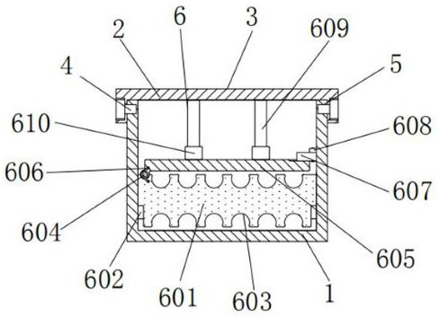
[0030]A cable tray equipped with adjustable wiring components includes a bracket 1. The top of the bracket 1 is fastened with a cover 2, and the outer wall of the cover 2 and the bracket 1 are coated with an anti-corrosion coating 3. The material of layer 3 is epoxy resin, and the anti-corrosion coating 3 can prevent the cover 2 and the bracket 1 from corrosion, thereby prolonging the service life. The outer wall of the cover 2 is equipped with bolts 4, and the inner wall of the bolts 4 The end is threadedly connected with the outer wall of the bracket 1 through the threaded groove 5, and the bolt 4 serves to fasten the cover body 2 and the bracket 1.

Embodiment 2

[0032]As an optional case, seefigure 1 with6, A cable tray with adjustable wiring components, wiring component 6 includes horizontal plate 601, bump 602, groove 603, round rod 604, pressure plate 605, torsion spring 606, bracket 607, clamp rod 608, vertical rod 609 and rubber In the sleeve 610, the outer wall of the horizontal plate 601 is in clearance fit with the inner wall of the bracket 1. The upper and lower ends of the horizontal plate 601 are provided with bumps 602. The outer ends of the bumps 602 are fixedly connected with the inner wall of the bracket 1 on the left and right sides. The inner side of the top of the block 602 is clamped with the outer end of the horizontal plate 601. The convex block 602 supports the horizontal plate 601. The inner side of the convex block 602 is provided with grooves 603, which are arranged horizontally and equidistantly. The grooves 603 are distributed in double rows with respect to the horizontal plate 601. This design can realize the dou...

Embodiment 3

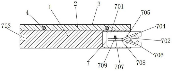
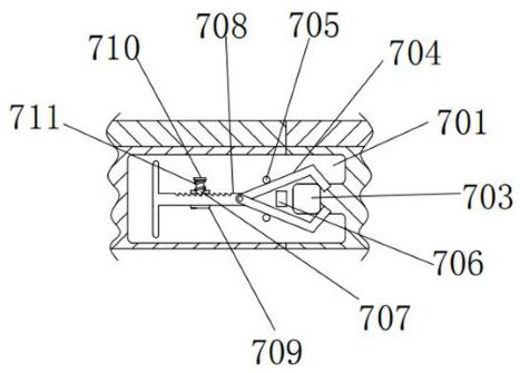
[0035]As an optional case, seeFigure 2-5, A cable tray with adjustable wiring components. Both sides of the front and left side of the bracket 1 are equipped with connecting components 7. The connecting components 7 include support plate 701, slot 702, insert block 703, clamp rod 704, short rod 705 , Top block 706, bayonet 707, rack 708, collar 709, baffle 710 and tension spring 711, the rear end of the support plate 701 is fixedly connected with the front right end of the bracket 1, and the right end of the support plate 701 is provided with an insert Slot 702, slot 702 is processed on the right end of support plate 701, the left side of slot 702 is provided with insert block 703, the rear end of insert block 703 is fixedly connected with the front left side of bracket 1, insert block 703 and slot 702 When the two brackets 1 are connected, they can be used for horizontal positioning. The front of the support plate 701 is provided with a clamping rod 704, the left end of the clampin...


PUM


Abstract

The invention discloses a cable bridge provided with an adjustable wiring assembly. The cable bridge comprises a supporting groove; a cover body is buckled at the top of the supporting groove; the wiring assembly is disposed in the supporting groove. According to the cable bridge with the adjustable wiring assembly, when the cable bridge with the adjustable wiring assembly is used, a pressing plate can be rotated from a vertical state to a horizontal state through rotary connection of the pressing plate and a transverse plate; a clamping rod can be transversely arranged at the top of the pressing plate to keep the pressing plate horizontal through abutting against the pressing plate, so that cables embedded in grooves at the upper side and low side of the transverse plate can be clamped; the cables are placed in the two rows of grooves, so that the number of the cables wired in the supporting groove is greatly increased, so that the use practicability and convenience are improved; theclamping rod is automatically unfolded through contacting with an ejector block. Compared with a traditional screw and nut fastening mode, the cable bridge can realize quick splicing of the supportinggroove, and shorten working time; and the cable bridge can be repeatedly used, so that the utilization rate of the cable bridge is greatly improved.

Description

Technical field[0001]The invention relates to the technical field of cable trays equipped with adjustable wiring components, in particular to a cable tray equipped with adjustable wiring components.Background technique[0002]The cable bridge is divided into trough type, tray type, ladder type, net format and other structures. It is composed of brackets, support arms and installation accessories. The bridge in the building can be erected independently or laid in various buildings (structures). And the pipe gallery bracket should reflect the characteristics of simple structure, beautiful appearance, flexible configuration and convenient maintenance. All parts need to be galvanized and installed on the open-air bridge outside the building. There are multiple cables installed inside the cable bridge. The cable supports high-definition video transmission and accurate data transmission as well as KVM (keyboard, monitor and mouse) technology.[0003]When using the cable tray with adjustable w...

Claims


Application Information

Patent Timeline
IPC IPC(8): H02G3/04
CPCH02G3/0406
Inventor 不公告发明人
Owner 苏州三木知识产权服务有限公司
Learn More