Magnetic-adsorption-type oil well optical cable capable of being adsorbed on inner side of metal pipe wall of oil and gas well

A metal tube, magnetic suction technology, used in wellbore/well components, optical fiber/cable installation, optics, etc., can solve the problems of inability to adhere to the inner wall of the casing, increase the degree of acoustic wave energy loss, etc., to reduce losses and increase. Acoustic wave sensitivity, the effect of increasing the response amplitude

Inactive Publication Date: 2019-12-27
OPTICAL SCI & TECH (CHENGDU) LTD +2
View PDF0 Cites 6 Cited by
  • Summary
  • Abstract
  • Description
  • Claims
  • Application Information

AI Technical Summary

Problems solved by technology

[0004] Based on the above problems, the present invention provides a magnetic oil well optical cable that can be adsorbed on the inner side of the metal pipe wall of the oil and gas well, which is used to solve the problem that the existing oil well optical cable is suspended in the center of the casing and cannot be closely attached to the inner wall of the casing, thereby Added issues with the degree of loss of acoustic energy as it is transferred from the bushing to the cable

Method used


Image

  • Magnetic-adsorption-type oil well optical cable capable of being adsorbed on inner side of metal pipe wall of oil and gas well
  • Magnetic-adsorption-type oil well optical cable capable of being adsorbed on inner side of metal pipe wall of oil and gas well
  • Magnetic-adsorption-type oil well optical cable capable of being adsorbed on inner side of metal pipe wall of oil and gas well

Examples


Embodiment 1

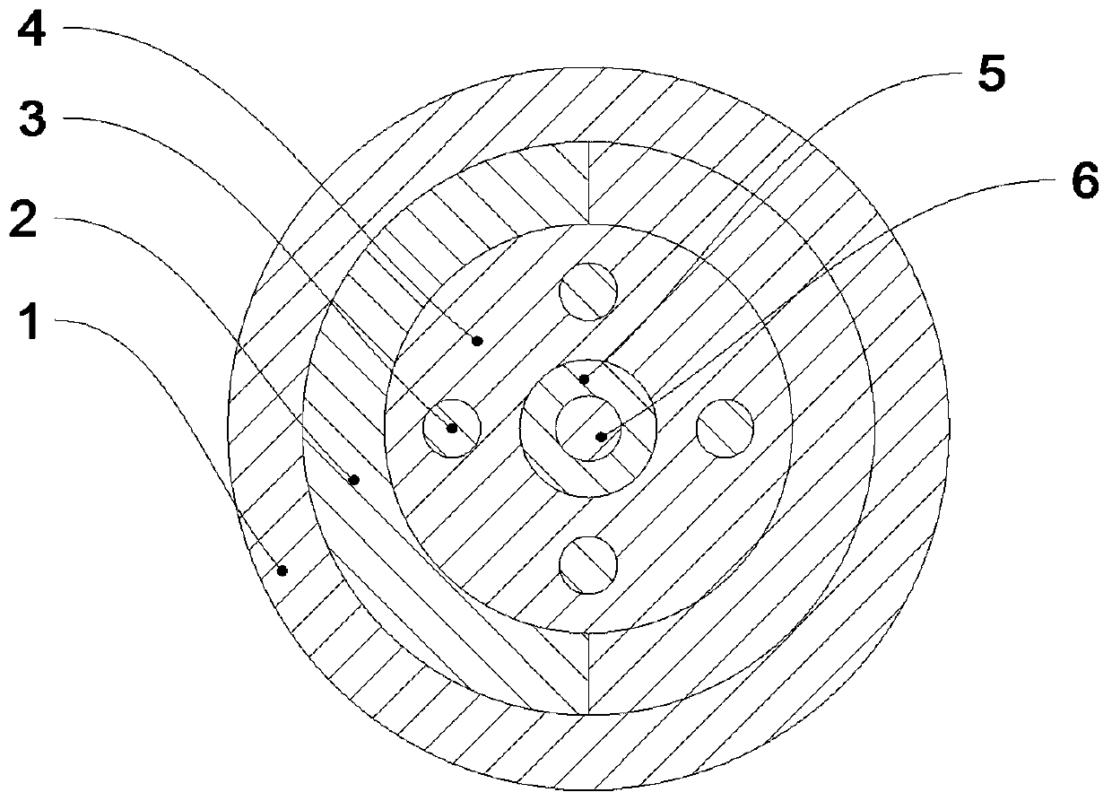
[0032] Such as Figure 1-6 As shown, a magnetic oil well optical cable that can be adsorbed on the inner side of the metal pipe wall of an oil and gas well includes a coated optical fiber 6, and a tight cladding 5 is attached to the outer surface of the coated optical fiber 6, and the outer surface of the tight cladding 5 A reinforcement layer is attached to the upper surface, and an adsorption element capable of absorbing the sleeve is attached to the outer surface of the reinforcement layer, and a protective layer 1 is attached to the outer surface of the adsorption element.

[0033] Working principle: When the optical cable is passed through the sleeve, since the optical cable is equipped with an adsorption element that can absorb the sleeve, the optical cable is tightly attached to the inner wall of the sleeve by using the adsorption force of the adsorption element on the sleeve. When the external sound wave When the energy is transferred to the casing, the acoustic energy...

Embodiment 2

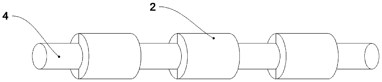
[0036] Such as Figure 1-4 As shown, on the basis of Example 1, this embodiment provides a preferred mechanism of the adsorption element, that is, the adsorption element is a plurality of sets of magnet assemblies 2 wrapped on the outer surface of the reinforcement layer, and the plurality of sets of magnet assemblies 2 are coated along the The length direction of the optical fiber 6 is distributed at intervals.

[0037] Preferably, the magnet assembly 2 includes a left semicircular magnet 21 and a right semicircular magnet 22, and the left semicircular magnet 21 and the right semicircular magnet 22 attract each other and are closely attached to the outer surface of the reinforcement layer.

[0038] Preferably, the length of the magnet assembly 2 is 5mm-30mm.

[0039]In this embodiment: the cross section of the left semicircular magnet 21 and the right semicircular magnet 22 can be a semicircular ring, and two magnets with the same shape and size attract each other to form a ...

Embodiment 3

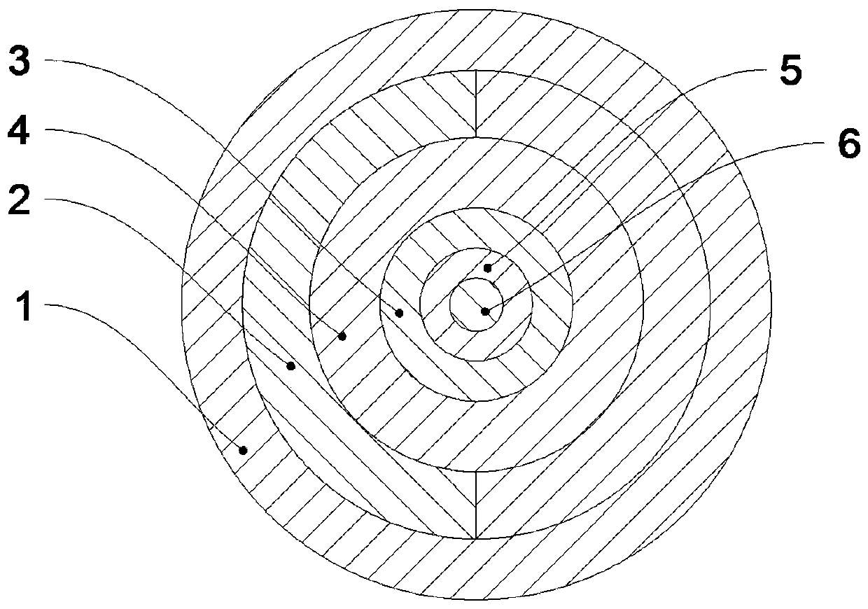
[0042] Such as Figure 5-6 As shown, on the basis of Example 1, this embodiment provides another preferred structure of the adsorption element, that is, the adsorption element includes a strip-shaped film 7 attached to the reinforcement layer, and the strip-shaped film 7 is provided with a plurality of Thin magnet blocks 8 , a plurality of thin magnet blocks 8 are distributed at intervals along the length direction of the coated optical fiber 6 .

[0043] Preferably, the strip-shaped film 7 is a single-layer film, and a plurality of thin magnet blocks 8 are attached to the outer surface of the single-layer film; or the strip-shaped film 7 is a double-layer film, and a plurality of thin magnet blocks 8 are arranged in the double-layer film .

[0044] Preferably, the thickness of the thin magnet block 8 is 0.5mm-2mm, and the shape of the thin magnet block 8 is rectangular, circular or elliptical.

[0045] In this embodiment, the thin magnet block 8 can be packaged and fixed in...


PUM


Abstract

The invention relates to the technical field of optical fiber sensing, in particular to a magnetic-adsorption-type oil well optical cable capable of being adsorbed on the inner side of a metal pipe wall of an oil and gas well. The problem that the degree of loss during the process that acoustic wave energy is transmitted from a bushing to an optical cable is increased due to the fact that the existing oil well optical cable is hung in the middle of the inner part of the bushing and cannot be tightly attached to the inner wall of the bushing is solved. The magnetic-adsorption-type oil well optical cable includes a coated optical fiber, a tight cladding layer is tightly attached to the outer surface of the coated optical fiber, a reinforcing layer is tightly attached to the outer surface ofthe tight cladding layer, adsorption parts capable of adsorbing a bushing are tightly attached to the outer surface of the reinforcing layer, and a protective layer is tightly attached to the outer surfaces of the adsorption parts. The adsorption parts can be tightly attached to the inner wall of the bushing, and external acoustic wave energy is directly applied to the optical cable after being transmitted to the bushing, the loss during the process of the acoustic wave energy being transmitted from the bushing to the optical cable is reduced, so that the response amplitude of the optical fiber to the external acoustic energy is improved, and the acoustic wave sensitivity of a distributed acoustic wave sensing cable is increased.

Description

technical field [0001] The invention relates to the technical field of optical fiber sensing, and more specifically relates to a magnetic suction oil well optical cable that can be adsorbed on the inner side of metal pipe walls of oil and gas wells. Background technique [0002] Optical fiber, short for optical fiber, is a fiber made of glass or plastic that acts as a means of conduction. Optical fiber distributed acoustic wave sensing technology is more and more widely used in oil and gas exploration and development, downhole production operation status monitoring, seismic monitoring and other fields. It uses optical fiber to have the dual functions of signal transmission and sensing, and does not require external sensors. , only need to connect a test instrument at one end of the optical cable, and analyze the geological structure, oil and gas distribution around the optical cable and other information by detecting the micro-strain condition caused by external acoustic ene...

Claims


Application Information

Patent Timeline
Patent Type & Authority Applications(China)
IPC IPC(8): E21B47/12G01V1/22G02B6/44G02B6/50
CPCG01V1/226G02B6/443G02B6/4415G02B6/50
Inventor 张仁志
Owner OPTICAL SCI & TECH (CHENGDU) LTD
Why Eureka
Try Eureka