Frequency signal generating circuit and liquid level detecting circuit

A technology for generating circuit and frequency signals, applied in liquid/fluid solid measurement, liquid level indicator for physical variable measurement, measurement device, etc., can solve problems such as high power requirements, and achieve the effect of stable water level and voltage

Pending Publication Date: 2019-12-27
GREE ELECTRIC APPLIANCES INC
View PDF0 Cites 3 Cited by
  • Summary
  • Abstract
  • Description
  • Claims
  • Application Information

AI Technical Summary

Problems solved by technology

[0005] Therefore, the technical problem to be solved by the present invention is to overcome the problem in the prior art that high-frequency AC signals generated by positive and negative voltages are required as excitation sources when detecting the water level of an electric kettle, and the problem of high requirements for power is provided, thereby providing a A frequency signal generation circuit and a liquid level detection circuit

Method used


Image

  • Frequency signal generating circuit and liquid level detecting circuit
  • Frequency signal generating circuit and liquid level detecting circuit
  • Frequency signal generating circuit and liquid level detecting circuit

Examples


Embodiment 1

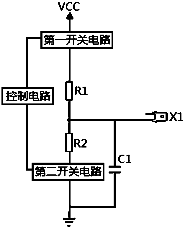
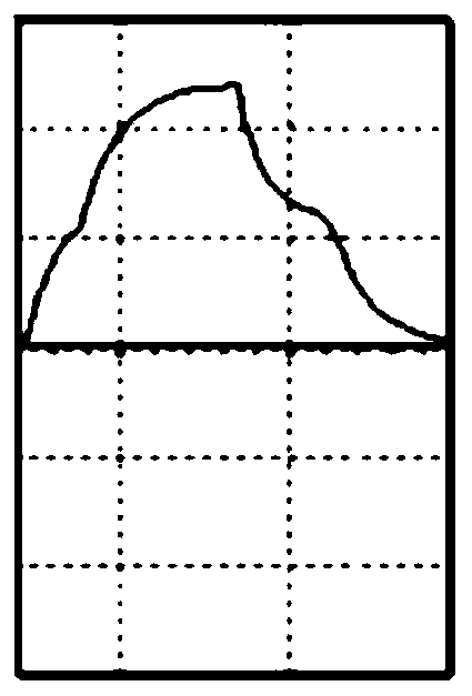
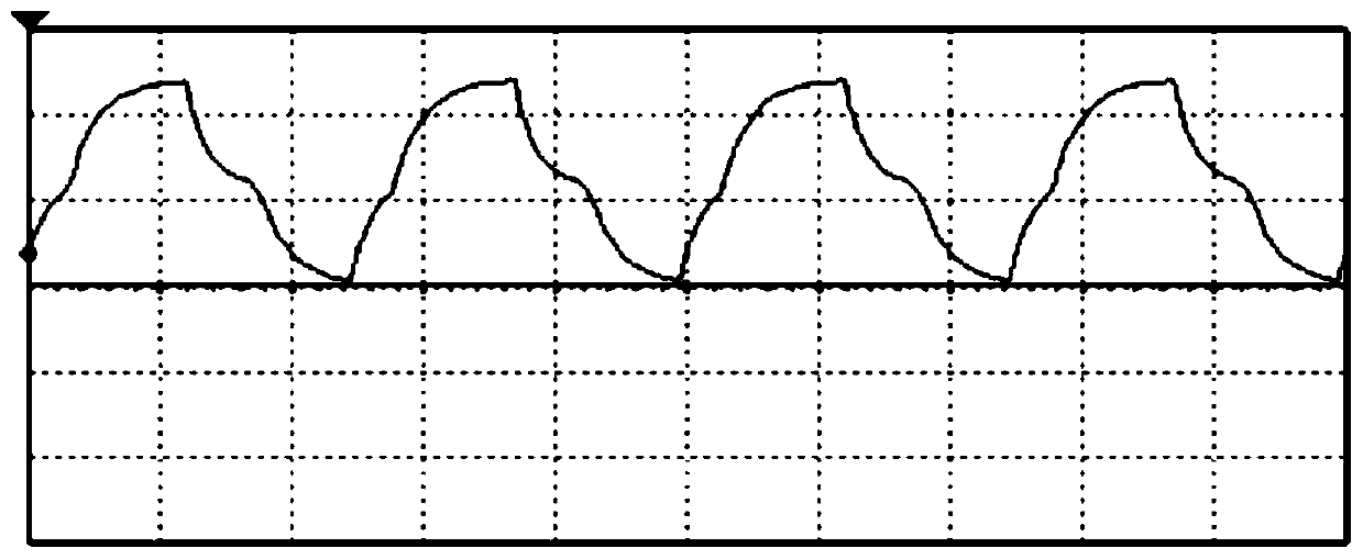
[0037] The frequency signal generation circuit is used to control the charge and discharge of the first capacitor C1 to generate a pulsating DC voltage signal. In this embodiment, the first switch circuit is the first switch S1, the second switch circuit is the second switch S2, and the control circuit is the controller for illustration. Such as figure 1 As shown, specifically, when the controller controls the first switch S1 to be turned on and the second switch S2 to be turned off, the DC power supply VCC charges the first capacitor C1 through the first resistor R1, and the voltage across the first capacitor C1 continues to increase. ; When the controller controls the first switch S1 to be disconnected and the second switch S2 to be closed, the first capacitor C1, the second resistor R2 and the ground form a closed loop, the first capacitor C1 is discharged, and the voltage across the first capacitor C1 is constant decrease. Such as figure 2 As shown, the voltage across ...

Embodiment 2

[0041] Such as Figure 4 As shown, the embodiment of the present invention provides a frequency signal generation circuit, wherein the control circuit is the PWM signal output terminal of the main control chip, the first switch circuit includes a bias resistor R4 and a first triode Q1, and the second switch The circuit includes a bias resistor R5 and a second transistor Q2. The first transistor Q1 is a PNP transistor, and the second transistor Q2 is an NPN transistor.

[0042] In this embodiment, the high level of the PWM signal output terminal should not be higher than the DC power supply VCC, which can be set by those skilled in the art according to the actual situation, which is not limited in this embodiment.

[0043] The bias resistor R4 and the bias resistor R5 are connected in parallel to the PWM signal output terminal of the main control chip, the base of the first triode Q1 is connected to the other end of the bias resistor R4, the emitter is connected to the DC powe...

Embodiment 3

[0050] Such as Figure 5 As shown, the embodiment of the present invention provides a frequency signal generation circuit. In the frequency signal generation circuit, the control circuit includes a main control chip, a bias resistor R6, a third triode Q3, a bias resistor R7 and a fourth Transistor Q4. The first switch circuit includes a bias resistor R4 and a first transistor Q1, and the second switch circuit includes a bias resistor R5 and a second transistor Q2. The first transistor Q1 is a PNP transistor, the second transistor Q2 is an NPN transistor, the third transistor Q3 is an NPN transistor, and the fourth transistor Q4 is a PNP transistor.

[0051] The PWM signal output terminal of the main control chip is connected in parallel with the bias resistor R6 and the bias resistor R7 at the same time, the base of the third transistor Q3 is connected to the other end of the bias resistor R6, the emitter is grounded, and the collector is connected to the bias resistor Conne...


PUM


Abstract

The invention discloses a frequency signal generating circuit and a liquid level detecting circuit, and the frequency signal generating circuit comprises the following parts of a DC power source VCC,a first switch circuit, a first resistor R1, a second resistor R2 and a second switch circuit that are connected in series, wherein the other end of the second switch is grounded; the first switch circuit and the second switch circuit are respectively connected to a control circuit for controlling the on/off thereof; and a first capacitor C1 connected in parallel with the second resistor R2 and the second switch circuit, wherein a first joint X1 is connected between the first resistor R1 and the second resistor R2. The invention controls the opening and closing cycles of the first switch circuit and the second switch circuit to control the charging and discharging of the first capacitor C1, thereby generating a high-frequency AC signal. High-frequency AC signals can be generated by using only a DC power source, thereby simplifying requirements on the power source.

Description

technical field [0001] The invention relates to the field of electronic circuits, in particular to a frequency signal generation circuit and a liquid level detection circuit. Background technique [0002] With the gradual improvement of people's living standards, many intelligent household appliances are gradually favored by people. At present, the electric kettles sold on the market use steam intelligent induction temperature control, which has the functions of automatic power off after boiling water and anti-dry power off. With the needs of life, the current electric kettle is also developing in a multi-functional direction, such as leak-proof, anti-scald, water-locking, etc. The electric kettle has the advantages of fast heating speed, good heat preservation effect, strong filtering function, and many styles. [0003] When a user uses an electric kettle with automatic water intake, as the water level of the electric kettle changes continuously, it is very important to d...

Claims


Application Information

Patent Timeline
Patent Type & Authority Applications(China)
IPC IPC(8): G01F23/26G05F1/56
CPCG01F23/266G05F1/561
Inventor 敬仕林郑丰周邓永文宁瀛锋
Owner GREE ELECTRIC APPLIANCES INC
Why Eureka
Try Eureka