

Convenient office system
An office system and a convenient technology, applied in general control systems, control/regulation systems, optical device exploration, etc., can solve the problems of office electrical equipment being turned on all the time, high office costs, and energy waste
Inactive Publication Date: 2017-12-08
贵州万广网络科技有限公司
View PDF7 Cites 2 Cited by
- Summary
- Abstract
- Description
- Claims
- Application Information
AI Technical Summary
Problems solved by technology
[0006] The present invention intends to provide a convenient office system, which can solve the problems that the electrical equipment in the office is always on after employees get off work, resulting in energy waste and high office costs, and is more convenient, fast and efficient
Method used
View moreImage
Smart ImageViewing Examples

Examples
Embodiment Construction
[0026] The present invention will be further described in detail below through specific implementations:
Login to View More PUM
 Abstract
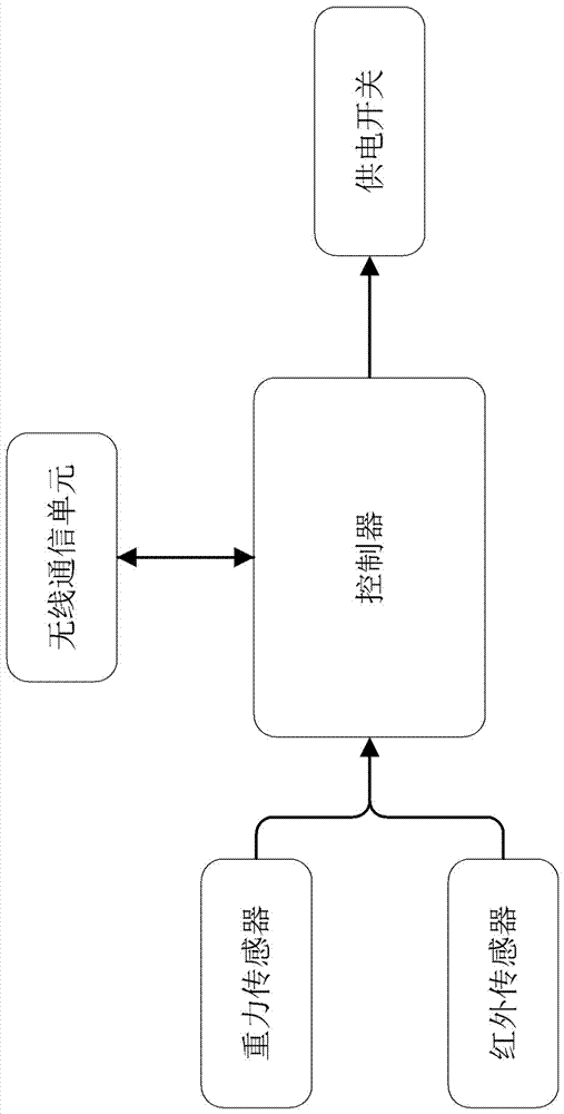
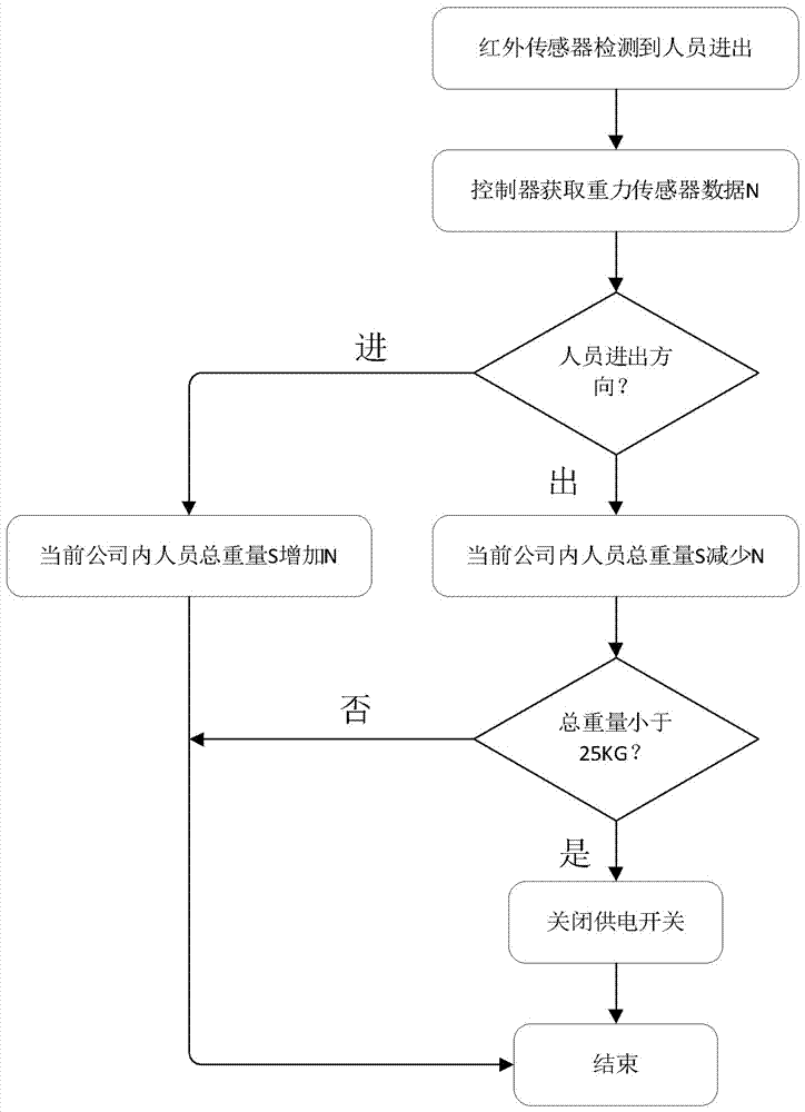
The invention relates to the technical field of office systems, and particularly relates to a convenient office system comprising a personnel access detection module and a master control module. The personnel access detection module comprises a gravity detection component and an infrared detection component. The master control module comprises a controller, a wireless communication unit and an enabling button. The gravity detection component is used for detecting the weight of personnel accessing to the company. The infrared detection component is used for detecting the personnel and the access direction of the personnel. The controller can acquire the data of the gravity detection component when the infrared detection component detects the personnel. The controller can perform statistics of the total weight of all the personnel of the current company according to the data of the infrared detection component and the gravity detection component and can control on and off of the power supply switch according to the total weight of all the personnel of the current company. According to the convenient office system, the problems of waste of energy resources and high office cost caused by the fact that the electricity utilization equipment of the office room is still on after work of the employees can be solved so that the system is more convenient, rapid and efficient in comparison with the present technical scheme.
Description
Technical field [0001] The present invention relates to the technical field of office systems, in particular to a convenient office system. Background technique [0002] The office is a place where people work. There are many kinds of electrical equipment in the office. Due to the fast pace of get off work now, everyone is anxious when off work, and often forgets to turn off the desk lamp and water heater in their office. Wait for electrical appliances, which caused unnecessary energy waste and increased office costs. [0003] In order to save energy, environmental protection and operating expenses, some companies will ask the person who left the company last to turn off the company's power supply switch, or assign a fixed person, such as a cleaner, to turn off the company's power supply switch after all employees leave, but leave the company at the end People often find it difficult to determine whether they are the last to leave. The cleaners have to constantly check and ask whet...
Claims
Login to View More Application Information
Patent Timeline
 IPC IPC(8): G05B19/048G01G19/44G01P13/04G01V8/10
CPCG05B19/048G01G19/44G01P13/04G01V8/10
Inventor熊飞
Owner贵州万广网络科技有限公司