Plasma thruster steady-state ion flow field measurement device and measurement method

A technology of ion flow field and plasma, which is applied in the field of ion plasma thruster steady-state ion flow field measurement device, can solve the problems of inability to obtain ion velocity vector angle, inability to obtain ion velocity vector angle distribution, etc.

Active Publication Date: 2019-12-27
BEIJING INST OF CONTROL ENG
View PDF9 Cites 6 Cited by
  • Summary
  • Abstract
  • Description
  • Claims
  • Application Information

AI Technical Summary

Problems solved by technology

The patent documents of Chinese patents CN105116435A and CN105116436A disclose the method of synchronous measurement of the ion flow field using the Faraday probe array, and the Faraday probe used in it adopts a conventional probe structure design, so the vector angular distribution of the ion velocity cannot be obtained
In the document "Magnetically filtered faraday probe for measuring the ion current density profile of ahall thruster", the Faraday probe can only be used to measure the ion current density of the thruster, but cannot obtain the vector angle of the ion velocity

Method used


Image

  • Plasma thruster steady-state ion flow field measurement device and measurement method
  • Plasma thruster steady-state ion flow field measurement device and measurement method
  • Plasma thruster steady-state ion flow field measurement device and measurement method

Examples


specific Embodiment

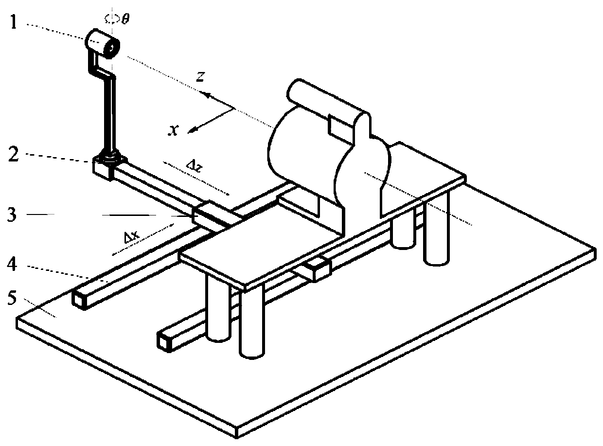
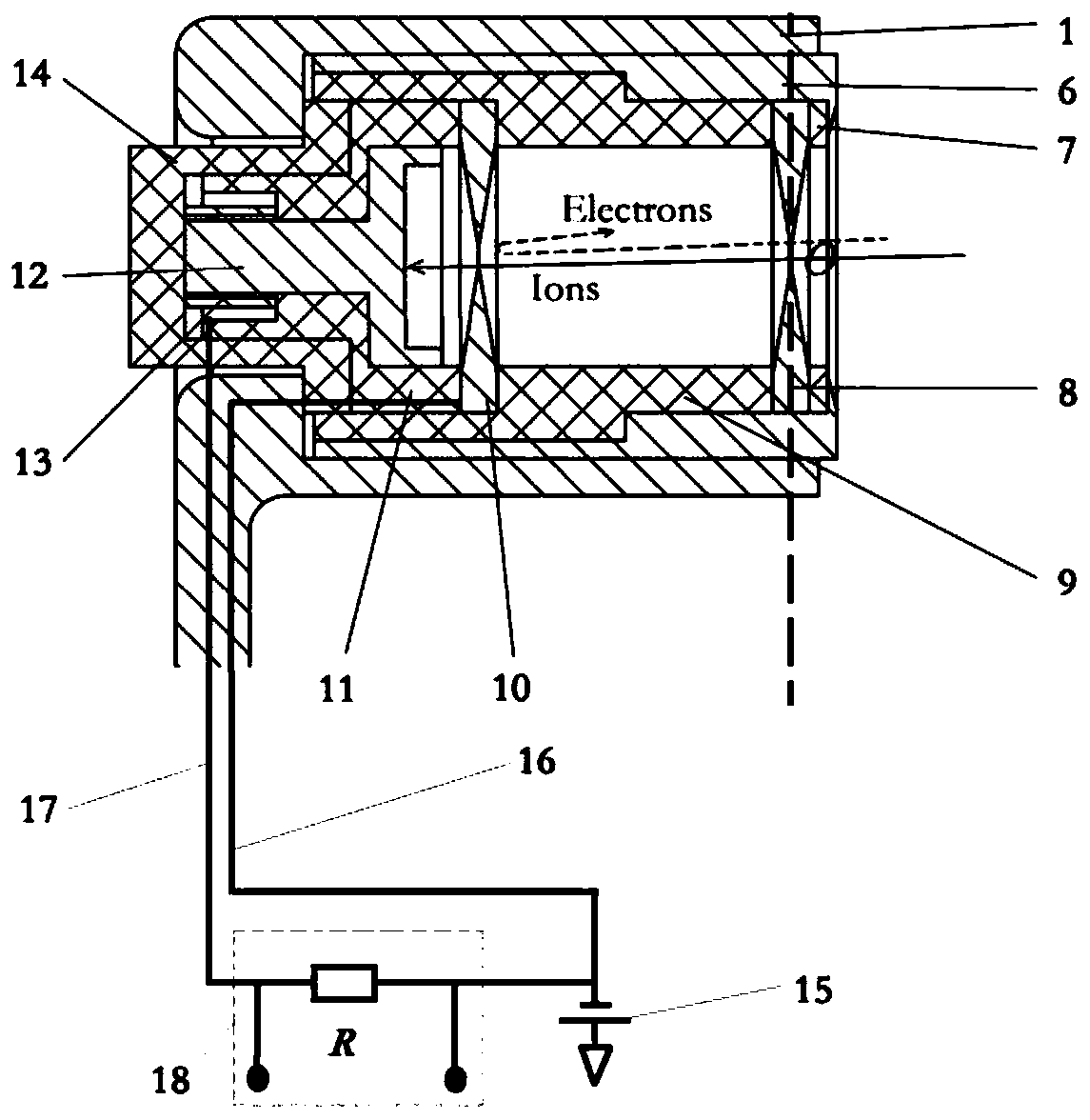
[0050] Such as figure 1 and 2 As shown, the present embodiment provides a measuring device capable of obtaining the current density of the ion steady-state flow field and the ion velocity vector information in the plume field, including a probe bracket 1, an electric turntable 2, a z-axis telescopic rod 3, and an X-direction Slide rail 4, probe fixing base 5, front top cover 6, insulating ceramic ring 7, incident grid 8, second housing 9, outgoing grid 10, insulating ceramic seat 11, ion receiving electrode 12, inner nut 13, first Housing 14 , bias power supply 15 , bias power supply line 16 , signal line 17 and signal acquisition circuit 18 .

[0051] The X-direction slide rail 4 and the z-axis telescopic rod 3 are sequentially installed on the probe fixing base 5 , the electric turntable 2 is fixed at the end of the z-axis telescopic rod 3 , and the probe bracket 1 is installed on the electric turntable 2 . Adjust the X-direction slide rail 4 and the Z-axis telescopic rod ...


PUM


Abstract

The embodiment of the invention provides a plasma thruster steady-state ion flow field measurement device and a measurement method and belongs to the technical field of steady-state ion flow field measurement. The device comprises a measurement module, a power supply module and a probe assembly, the probe assembly comprises a probe, a probe support and an electric rotary table, the probe comprisesan insulation shell, an ion receiving pole, an incident gate and an emergent gate, one end of the insulation shell is open, the incident gate is located at the opening of the insulation shell, the emergent gate is located at the middle part of the inner cavity of the insulation shell, the ion receiving pole is located at one section, far away from the incident gate, in the inner cavity of the insulation shell, an incident hole of the incident gate and an emergent hole of the emergent gate are coaxial, the ion receiving pole, the incident gate and the emergent gate are mutually insulated, theinsulation shell is fixed on the probe support, and the electric rotary table is used for driving the probe support to rotate around the incident hole of the incident gate. The device provided by theembodiment of the invention can obtain an ion current density distribution function on each azimuth angle of a measurement point by enabling the probe to rotate around the measurement point, and a vector angle of an ion velocity is obtained at the same time.

Description

technical field [0001] The invention relates to the technical field of steady-state ion flow field measurement, and in particular provides a plasma thruster steady-state ion flow field measurement device and a measurement method. Background technique [0002] The Hall thruster is a very typical plasma electric propulsion device in the international field. Plasma thrusters rely on high-speed plasma plumes to generate reaction thrust, and their working efficiency depends on the distribution characteristics of the steady-state ion flow field in the plume region. Therefore, obtaining the steady-state ion flow field distribution in the plume region is of great significance for the optimization of thruster performance. [0003] Due to the complex ionization acceleration process of the plasma thruster, the ion flow field in the plume region has a very complex spatial structure. In this ion flow field, obtaining the ion current density distribution and its velocity vector angle at...

Claims


Application Information

Patent Timeline
Patent Type & Authority Applications(China)
IPC IPC(8): G01T1/29
CPCG01T1/29G01T1/2914
Inventor 胡鹏沈岩毛威扈延林胡大为吴朋安山世华藏娟伟李胜军吴耀武李栋
Owner BEIJING INST OF CONTROL ENG
Why Eureka
Try Eureka