Relay protection configuration and setting method for high-voltage power distribution system of ferroalloy electric furnace

A technology of relay protection and high-voltage power distribution, applied in emergency protection circuit devices, protection against overcurrent, emergency protection devices with automatic disconnection, etc. Remove faults and other problems to achieve the effect of improving service life and prolonging service life

Active Publication Date: 2019-12-10
鞍钢集团工程技术有限公司
View PDF3 Cites 2 Cited by
  • Summary
  • Abstract
  • Description
  • Claims
  • Application Information

AI Technical Summary

Problems solved by technology

[0007] At present, before the ferroalloy electric furnace is put into operation, there are no national unified standards and regulations for the relay protection setting of the microcomputer, so that the configuration scheme and setting of the relay protection remain on the traditional relay scheme, and the protection scheme is too simple. There are two schemes of "quick break" and "definite time" protection, which cannot meet the operation of modern large-scale submerged arc furnace equipment, especially in places where the high voltage side is a neutral point ungrounded system or is far away from the power system. Due to the small fault current, according to The configuration setting method in Table 1 cannot meet the action requirements and cannot quickly remove the fault

Method used


Image

  • Relay protection configuration and setting method for high-voltage power distribution system of ferroalloy electric furnace
  • Relay protection configuration and setting method for high-voltage power distribution system of ferroalloy electric furnace
  • Relay protection configuration and setting method for high-voltage power distribution system of ferroalloy electric furnace

Examples


Embodiment Construction

[0063] The specific embodiments provided by the present invention will be described in detail below in conjunction with the accompanying drawings.

[0064] The present invention provides a relay protection configuration scheme and a mathematical model of inverse time-limit overload relay protection. The relay protection scheme is shown in Table 2. A relay protection configuration and setting method for a ferroalloy electric furnace high-voltage power distribution system is organized as follows :

[0065] Table 2 Relay protection configuration and setting calculation of ferroalloy furnace transformer

[0066]

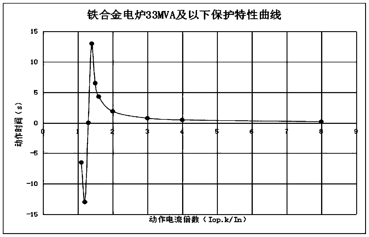
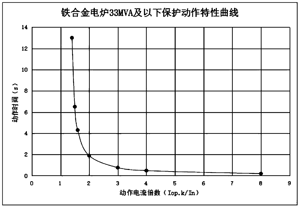
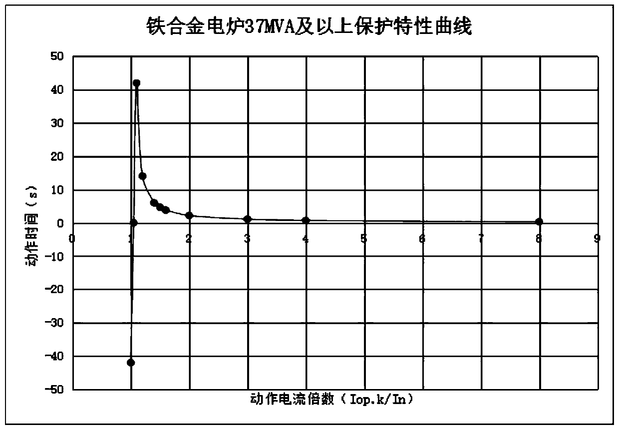
[0067] Such as Figure 5-7 Shown:

[0068] 1) The current quick-break protection is used as the main protection, which is mainly set for short-circuit faults inside the transformer. Due to the structural type of the ferroalloy furnace transformer, it is impossible for three-phase and two-phase short-circuit faults to occur inside the transformer (three single-phase ...


PUM


Abstract

The invention discloses a relay protection configuration and setting method for a high-voltage power distribution system of a ferroalloy electric furnace. The method comprises overload protection, instantaneous current quick-break protection and low-voltage locking overcurrent protection, wherein the instantaneous current quick-break protection serves as main protection, and is set to be effectivewhen a short-circuit fault occurs in the transformer; the low-voltage locking overcurrent protection serves as backup protection of the instantaneous quick-break protection and is set to be effectivewhen a small-current grounding fault of the transformer occurs; and inverse time limit overload protection has an inverse time limit characteristic, is used as backup protection of the instantaneousquick-break protection and the low-voltage blocking overcurrent protection, is matched with an operation curve of the ferroalloy electric furnace transformer by utilizing an inverse proportion relation between time and current, and does not act during normal production. Each kind of protection can be used as backup protection of the next kind of protection, especially in an ungrounded system withthe high voltage side being a neutral point or places away from an electric power system. Although the fault current is small, the applied low-voltage locking overcurrent protection and the inverse time limit overload protection can be effective.

Description

technical field [0001] The invention relates to the technical field of energy generation, supply and distribution, and in particular to a relay protection configuration and setting method for a high-voltage power distribution system of a ferroalloy electric furnace. Background technique [0002] The ferroalloy electric furnace transformer is a kind of submerged arc furnace transformer. Because its load characteristics are similar to those of the electric arc furnace transformer, the relay protection function of its electrical system is one of the most important technical indicators to ensure the safety and stable operation of the equipment, especially the overload Protect. At present, the main setting calculation methods are as follows: [0003] "Iron and Steel Enterprise Electric Power Design Manual" Volume 1 P706, the protection and setting calculation of the ferroalloy furnace transformer should be set according to the requirements of Table 1. [0004] Table 1 Setting c...

Claims


Application Information

Patent Timeline
Patent Type & Authority Applications(China)
IPC IPC(8): H02H7/04H02H3/08H02H3/10H02H3/05
CPCH02H7/04H02H3/08H02H3/105H02H3/05
Inventor 郑伟冯占立杨冶王罡世李鹏富钢巴月娥高贵军耿全德李子良殷业鹏于雷陈鹏超
Owner 鞍钢集团工程技术有限公司
Why Eureka
Try Eureka