Radio monitoring device

A technology of radio monitoring and electromagnetic board, which is applied in the direction of circuit layout, transmission monitoring, and electrical components on the supporting structure, which can solve problems affecting the timely use of devices, circuit board short circuit, and moving back and forth, so as to reduce the difficulty of repair and replacement , improve safety, and facilitate the effect of taking and placing

Active Publication Date: 2019-12-27
井翠红
View PDF14 Cites 0 Cited by
  • Summary
  • Abstract
  • Description
  • Claims
  • Application Information

AI Technical Summary

Problems solved by technology

[0003] Existing radio monitoring device has certain disadvantages when in use, (1), heat dissipation safety is insufficient: the heat dissipation mode of existing radio monitoring device is to send the outside air into the inside of the device through the cooling hole, and the inside of the device After the components exchange heat, they are discharged through the cooling holes to form a cycle. However, because the outside air contains a lot of moisture and dust, when the air enters the device, the moisture and dust in the air adhere to the surface of the circuit board. It is easy to cause situations such as circuit board short circuit; (2), repair and replacement inconvenience: when existing radio monitoring device is in use, needs to move back and forth, is convenient to detect the radio signal of different positions, so when needing to repair, can only use tool first The internal parts of the device can only be repaired after the shell of the device is disassembled. Since the repair takes a certain amount of time, it affects the timely use of the device. For this reason, we propose a radio monitoring device

Method used


Image

  • Radio monitoring device
  • Radio monitoring device
  • Radio monitoring device

Examples


Embodiment Construction

[0028] In order to make the technical means, creative features, goals and effects achieved by the present invention easy to understand, the present invention will be further described below in conjunction with specific embodiments.

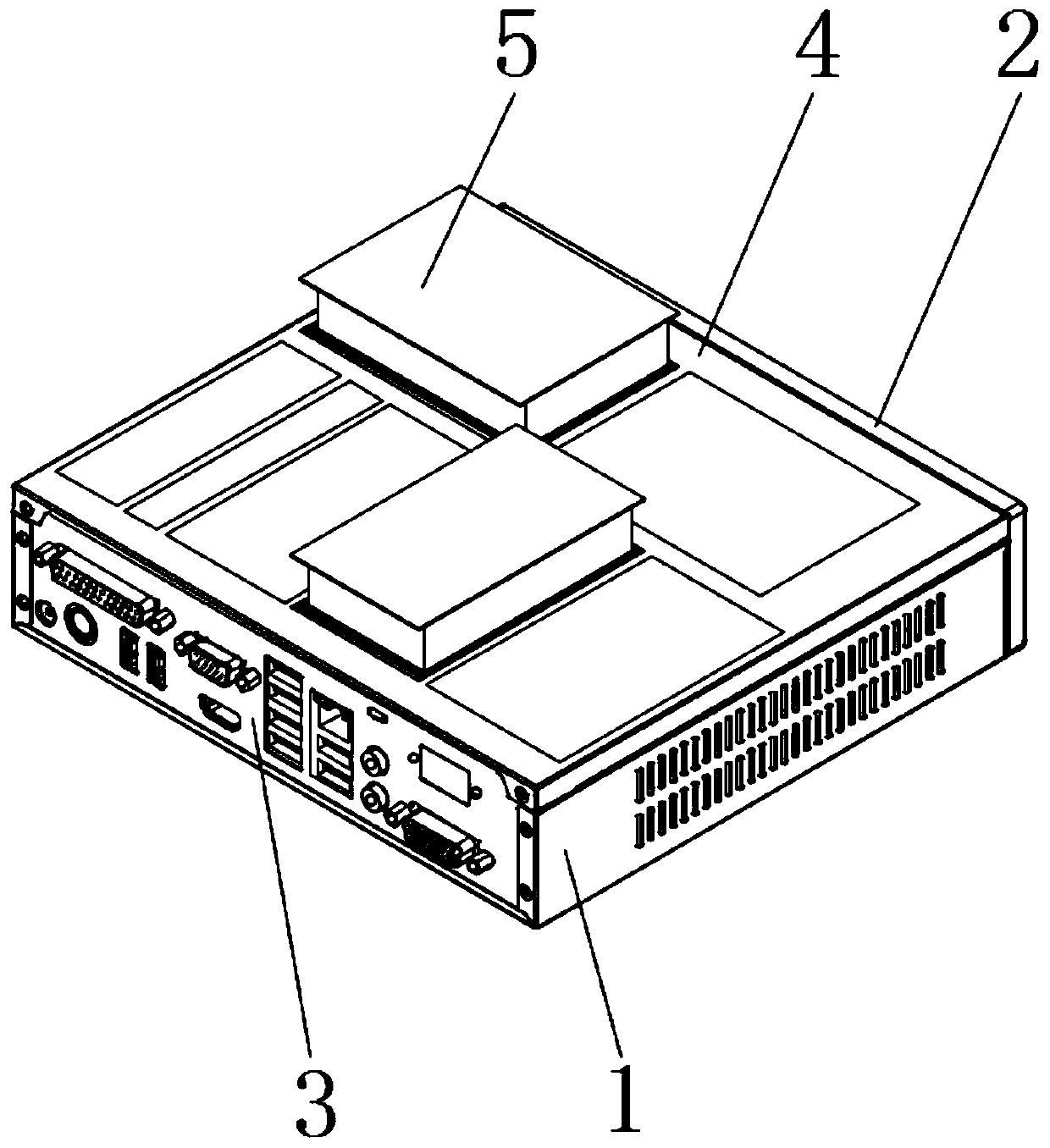
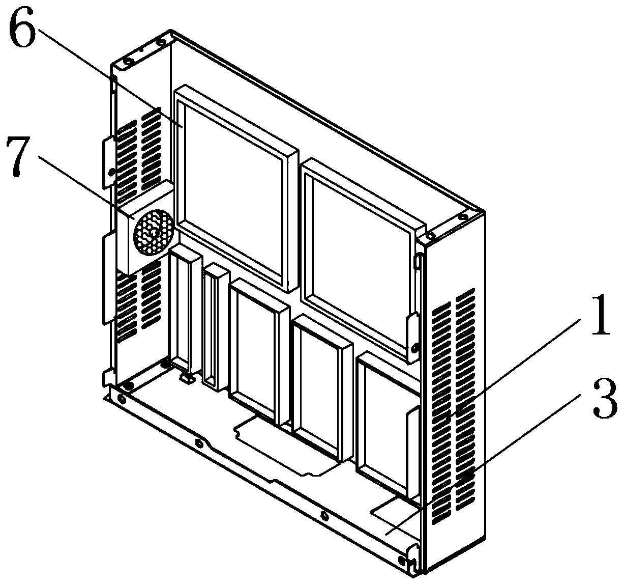
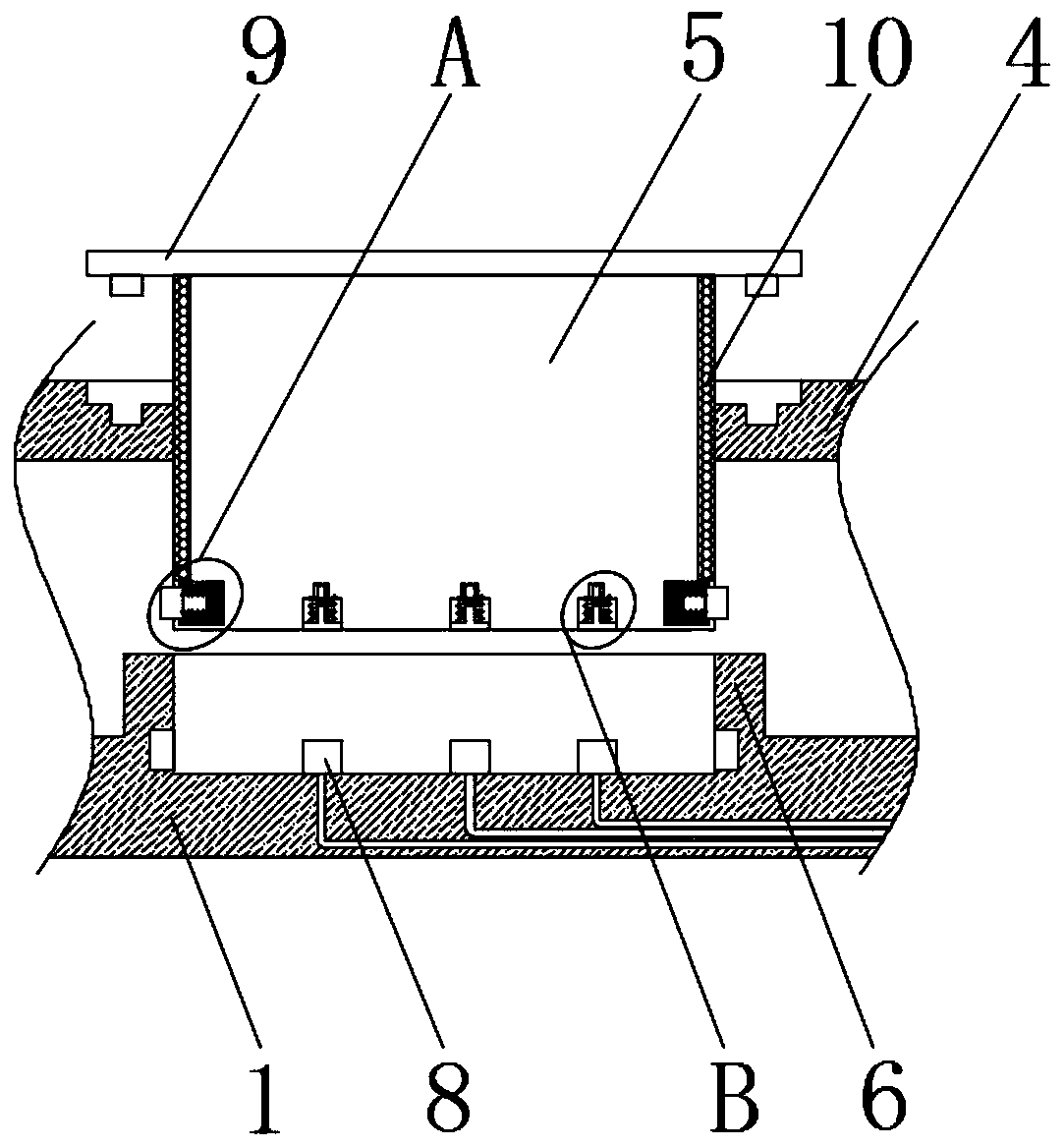
[0029] refer to Figure 1-3 As shown, a radio monitoring device includes a protective base 1, the outer surfaces of the front and rear ends of the protective base 1 are respectively fixed with a front baffle 3 and a rear baffle 2 by bolts, and the rear baffle 2 is located behind the front baffle 3 The outer surface of both sides of the protective base 1 is welded with heat dissipation plates, and the outer surface of the heat dissipation plate is equidistantly opened with a plurality of heat dissipation holes. The outer surface of the heat dissipation plate close to the protective base 1 is fixed with a heat dissipation fan 7 by bolts. , and the interior of the cooling fan 7 is provided with a driving motor and fan blades, the fan blades are fixed...


PUM


Abstract

The invention discloses a radio monitoring device. The device comprises a protection base; a front baffle and a rear baffle are fixedly installed on the outer surfaces of the front end and the rear end of the protection base through bolts respectively; the rear baffle is located behind the front baffle; heat dissipation plates are welded to the outer surfaces of two sides of the protection base; and a plurality of heat dissipation holes penetrating the heat dissipation plates are formed in the outer surfaces of the heat dissipation plates at equal intervals. The repair and replacement difficulty of the radio monitoring device can be reduced. The radio monitoring device can be assembled and disassembled. Components are installed in a device box; the outer surface of the device box is wrapped with a heat dissipation shell; and therefore, the components can be isolated from the outside; and heat on the surface of the heat dissipation shell can be taken away through air fed by a fan. A reserved groove is formed in the bottom end of the device box; a copper sheet is arranged on the inner top surface of the reserved groove; and therefore, the reserved groove can be prevented from being blocked by dust or chippings, and the use safety of the device can be improved.

Description

technical field [0001] The invention relates to the technical field of radio inspection and monitoring, in particular to a radio monitoring device. Background technique [0002] Radio monitoring refers to the activities of detecting, searching, and intercepting radio signals in the radio management area, and analyzing, identifying, monitoring and obtaining technical information such as technical parameters, working characteristics and radiation positions of the radio signals. It is an effective implementation An important means basis for radio management; [0003] Existing radio monitoring device has certain disadvantages when in use, (1), heat dissipation safety is insufficient: the heat dissipation mode of existing radio monitoring device is to send the outside air into the inside of the device through the cooling hole, and the inside of the device After the components exchange heat, they are discharged through the cooling holes to form a cycle. However, because the outsi...

Claims


Application Information

Patent Timeline
IPC IPC(8): H05K7/20H05K7/02H05K5/02H05K5/00H04B17/00
CPCH05K7/20145H05K7/023H05K5/0021H05K5/0217H04B17/00H05K5/03
Inventor 井翠红
Owner 井翠红
Why Eureka
Try Eureka