Automatic projection welding process method of robot

A process method and robot technology, applied in manufacturing tools, welding equipment, metal processing, etc., can solve problems such as unstable welding quality, low welding efficiency, and low production efficiency, and achieve automation, high production efficiency, and stable welding quality Effect

Inactive Publication Date: 2019-12-31
天津七所高科技有限公司
View PDF10 Cites 3 Cited by
  • Summary
  • Abstract
  • Description
  • Claims
  • Application Information

AI Technical Summary

Problems solved by technology

The disadvantages of manual projection welding are also obvious. The welding efficiency is low and the welding quality is unstable. Especially when the defective products flow into the OEM to the production and loading stage, this kind of error will lead to the scrapping of the whole vehicle and it is difficult to remedy.
Therefore, many auto parts manufacturing equipment manufacturers have developed semi-automatic projection welding machines or robot workstations. Similar projection welding equipment basically uses manual loading and unloading. Robots grab workpieces for welding, which is semi-automatic and requires operators to assist in production. , the production efficiency is still relatively low

Method used


Image

  • Automatic projection welding process method of robot
  • Automatic projection welding process method of robot

Examples


Embodiment Construction

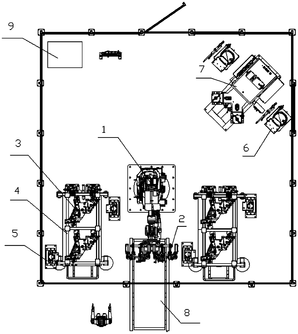
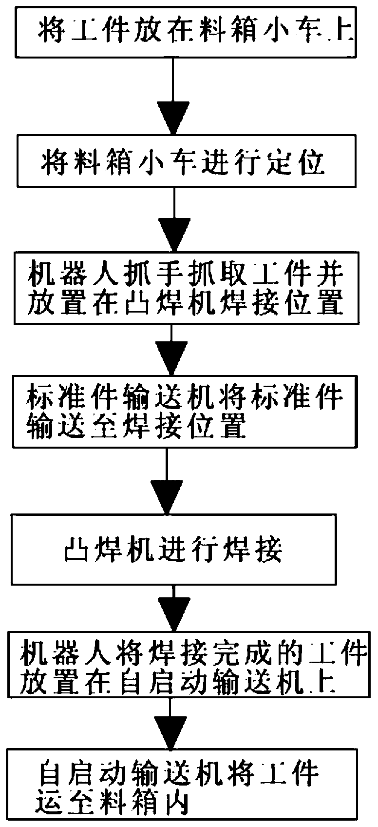
[0020] Robotic automatic projection welding process method, which includes the following process flow:

[0021] In the first step, the workpiece is manually placed on the workpiece fixture 3 of the workpiece fine positioning material box trolley 4;

[0022] In the second step, manually push the precise positioning material box trolley with the workpiece into the material box positioning mechanism 5 for positioning, and PLC 9 controls the material box positioning mechanism to lock the workpiece fixture; the sensor switch is installed on the material box positioning mechanism, When the induction switch detects the position of the trolley, press the confirmation button manually, and the PLC will control the material box positioning mechanism to automatically lock the precise positioning material box trolley.

[0023] In the third step, the PLC controls the robot 1 to grab the workpiece from the workpiece fixture with the gripper 2, and place the workpiece on the positioning mecha...


PUM


Abstract

The invention relates to the technical field of welding, in particular to an automatic projection welding process method of a robot. The method includes the following steps of firstly, putting a workpiece on a workpiece clamp of a workpiece fine positioning material box trolley manually; secondly, putting the fine positioning material box trolley into a material box positioning mechanism manually,and controlling the material box positioning mechanism by a PLC to lock the workpiece clamp; thirdly, grabbing the workpiece on the workpiece clamp by a grabber on the robot, and putting the workpiece on an automatic projection welding positioning mechanism; fourthly, conveying a standard workpiece to the welding position of an automatic projection welding machine by a standard workpiece conveyer; fifthly, making an upper electrode of the automatic projection welding machine press down to press tightly the workpiece and the standard workpiece for power-on welding, and combining the projectionwelding standard workpiece and a plate piece into a whole; and sixthly, moving the workpiece obtained after projection welding onto a self-start type conveying belt by the robot, and conveying the workpiece into a material box through the self-start type conveying belt. The process method is precise in positioning, stable in welding quality and high in automatic degree and production efficiency.

Description

technical field [0001] The invention relates to the field of welding technology, in particular to a robot automatic projection welding process method. Background technique [0002] As the first process after parts stamping, the projection welding process of auto parts requires high production cycle, stable and reliable welding quality, and it is necessary to prevent welding defects such as wrong welding and missing welding. The existing manual projection welding process is as follows: Manually transport the workpiece from the material box to the projection welding machine, align the workpiece hole and enter the lower electrode positioning pin of the projection welding machine, manually place the standard parts or screws, after the projection welding is completed, manually place the The workpiece is put into the finished product bin. This method is commonly used in most auto parts factories at present. The disadvantages of manual projection welding are also obvious. The wel...

Claims


Application Information

Patent Timeline
Patent Type & Authority Applications(China)
IPC IPC(8): B23K11/14B23K11/36
CPCB23K11/14B23K11/36B23K2101/006
Inventor 杨瑞军王勇洪涛龚蒙
Owner 天津七所高科技有限公司
Why Eureka
Try Eureka