
Anti-blocking sludge bin applicable to sludge with water content of 5-65%

A technology of water content and sludge, applied in loading/unloading, container, packaging and other directions, can solve the problems of restricting the stable operation of sludge treatment and disposal projects, difficult to break through sludge storage technology, environmental protection project obstacles, etc. Utilization rate, improving the scope of application, preventing the effect of sludge hardening

Active Publication Date: 2019-12-31
NANJING CEC ENVIRONMENTAL ENGINEERING CO LTD
View PDF8 Cites 0 Cited by
  • Summary
  • Abstract
  • Description
  • Claims
  • Application Information

AI Technical Summary

Problems solved by technology

During the continuous development and application of sludge treatment and disposal technology in China, the silo is required as an intermediate storage function. However, due to the characteristics of the sludge itself, such as stickiness and easy compaction, the discharge equipment will be blocked during the storage process, and the discharge volume will be difficult. Control and other problems, the current sludge storage technology is difficult to break through, which restricts the stable operation of sludge treatment and disposal projects and creates obstacles for environmental protection projects

Method used


Image

  • Anti-blocking sludge bin applicable to sludge with water content of 5-65%
  • Anti-blocking sludge bin applicable to sludge with water content of 5-65%
  • Anti-blocking sludge bin applicable to sludge with water content of 5-65%

Examples


Embodiment Construction

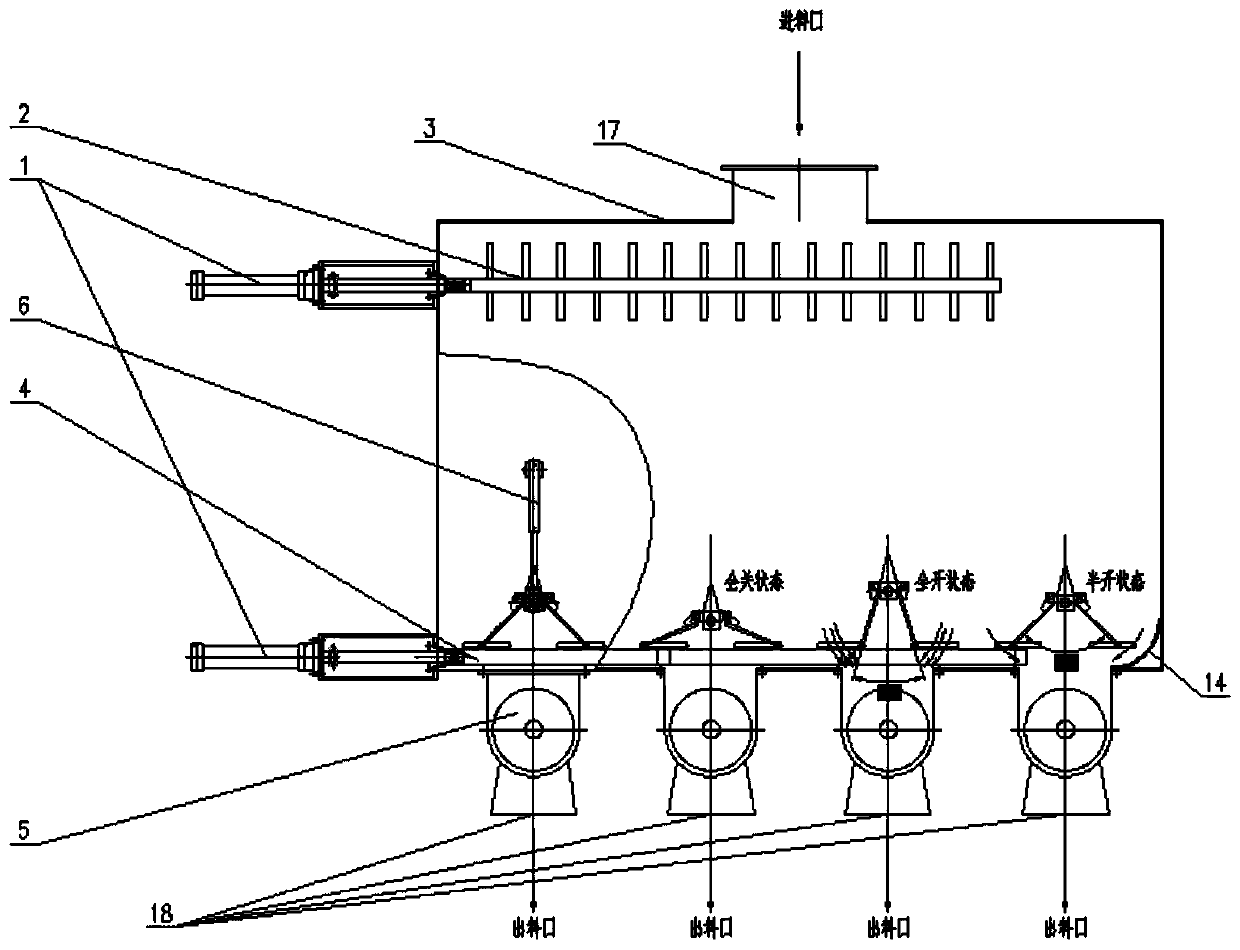
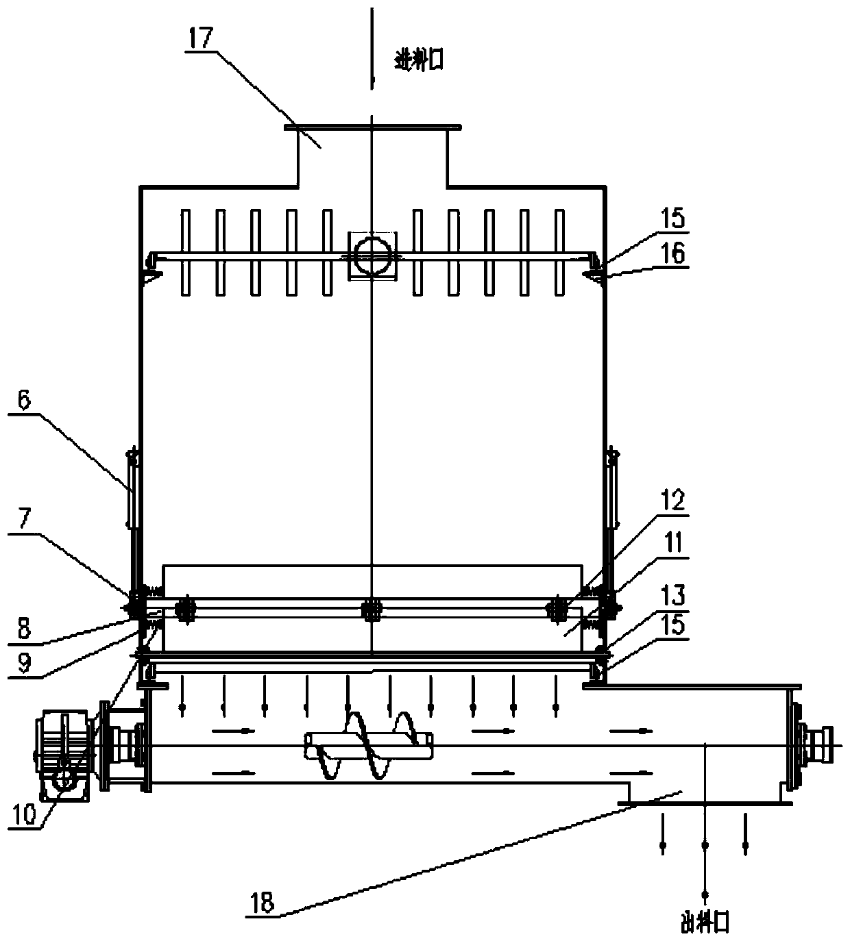
[0027] As shown in the figure, the present invention includes a bin body 3 and a screw conveyor 5 arranged at the bottom of the bin body 3 . The top of the bin body 3 is provided with a feed inlet 17, and the bottom is provided with a sludge outlet. The bin body 3 is provided with a movable sealing plate fixing seat 8, a movable sealing plate 11, a silo carriage 4, and an equalizer 2, and the sludge outlet at the bottom of the bin body 3 communicates with the feeding port of the screw conveyor 5. A circular arc plate 14 is installed at the bottom corner of the bottom of the bin body 3 opposite to the position of the bin carriage 4 .

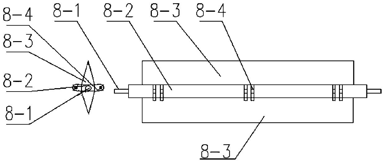
[0028] The movable sealing plate fixing seat 8 includes a shaft head 8-1, a fixing seat body 8-2, two triangular top baffles 8-3, a hinge fixing ear 8-4, and the shaft head 8-1 is welded to the fixing seat body 8-2 Fixing, two triangular top baffles 8-3 are welded and fixed with the upper and lower sides of the fixed seat body 8-2 respectively, ...


PUM


Abstract

The invention provides an anti-blocking sludge bin applicable to sludge with the water content of 5-65%. The anti-blocking sludge bin comprises a bin body, the top of the bin body is provided with a feeding inlet, the bottom of the bin body is provided with a sludge outlet, and a movable sealing plate capable of adjusting the opening degree of an opening and an adjusting mechanism for driving themovable sealing plate are arranged above the sludge outlet in the bin body. Spiral conveyers are arranged below the sludge outlet, and feed inlets of the spiral conveyers are communicated with the sludge outlet. In the anti-blocking sludge bin, the sludge in the bin can be controlled under the action of the sealing plate capable of adjusting the opening degree to flow into the spiral conveyers onthe lower side, and fed to discharging outlets under the conveying action of the spiral conveyers. The sealing plate capable of adjusting the opening degree can control the size of the discharging section area of the sludge outlet in the bottom of the bin body, when the sludge fluidity is high, the opening degree can be reduced, and the discharging capacity is thus reduced; when the sludge fluidity is low, the opening degree can be increased, and the discharging capacity is thus improved.

Description

technical field [0001] The invention relates to the technical field of sludge treatment and disposal, in particular to an anti-blocking sludge silo suitable for sludge with a water content of 5-65%. Background technique [0002] With the development of cities, the status of environmental protection is becoming more and more important. With the increase of urban sewage treatment rate, the sludge production has increased significantly, and the problem of sludge treatment has become more prominent. During the continuous development and application of sludge treatment and disposal technology in China, the silo is required as an intermediate storage function. However, due to the characteristics of the sludge itself, such as stickiness and easy compaction, the discharge equipment will be blocked during the storage process, and the discharge volume will be difficult. Control and other problems, the current sludge storage technology is difficult to break through, which restricts th...

Claims


Application Information

Patent Timeline
IPC IPC(8): B65D88/54B65D88/64B65G69/04
CPCB65D88/546B65D88/64B65G69/045
Inventor 王世兴张烨杨强
Owner NANJING CEC ENVIRONMENTAL ENGINEERING CO LTD
Learn More