Revolution-type semiconductor evaporation table

An evaporation table and semiconductor technology, applied in the semiconductor field, can solve the problems of low evaporation precision, uneven thickness of metal film, low efficiency of revolution type evaporation table, etc., and achieve high evaporation precision, good evaporation effect and high dryness. Effect

Pending Publication Date: 2019-12-31
苏州华楷微电子有限公司
View PDF0 Cites 0 Cited by
  • Summary
  • Abstract
  • Description
  • Claims
  • Application Information

AI Technical Summary

Problems solved by technology

The above two evaporation tables have the following advantages and disadvantages: the planetary evaporation table can evaporate multiple slide covers at one time, and multiple wafers are fixed on each slide cover, so more wafers can be evaporated at one time , but the evaporation accuracy of this evaporation table is not high. Since the slide cover is in an inclined state during evaporation, the distance between the wafer on the slide cover and the crucible is not equal. Therefore, the metal film obtained by evaporation Film thickness may not be uniform
On the common revolving evaporation table, since all the wafers are directly above the crucible, and the distance is equal, the pattern obtained by evaporation is more accurate, but since only one slide cover can be evaporated at a time, frequent opening of the cover is required. Frequent vacuuming, and the vacuuming time is longer than the evaporation time, so the efficiency of this rotary evaporation table is very low

Method used


Image

  • Revolution-type semiconductor evaporation table
  • Revolution-type semiconductor evaporation table
  • Revolution-type semiconductor evaporation table

Examples


Embodiment Construction

[0033] The present invention will be described in further detail below through specific examples.

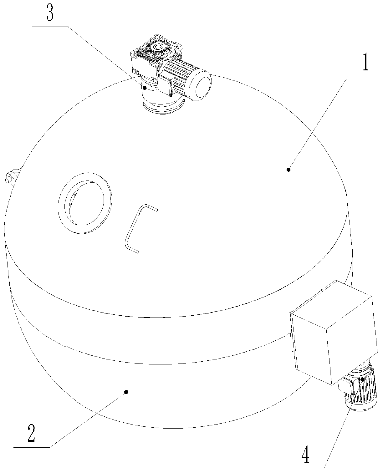
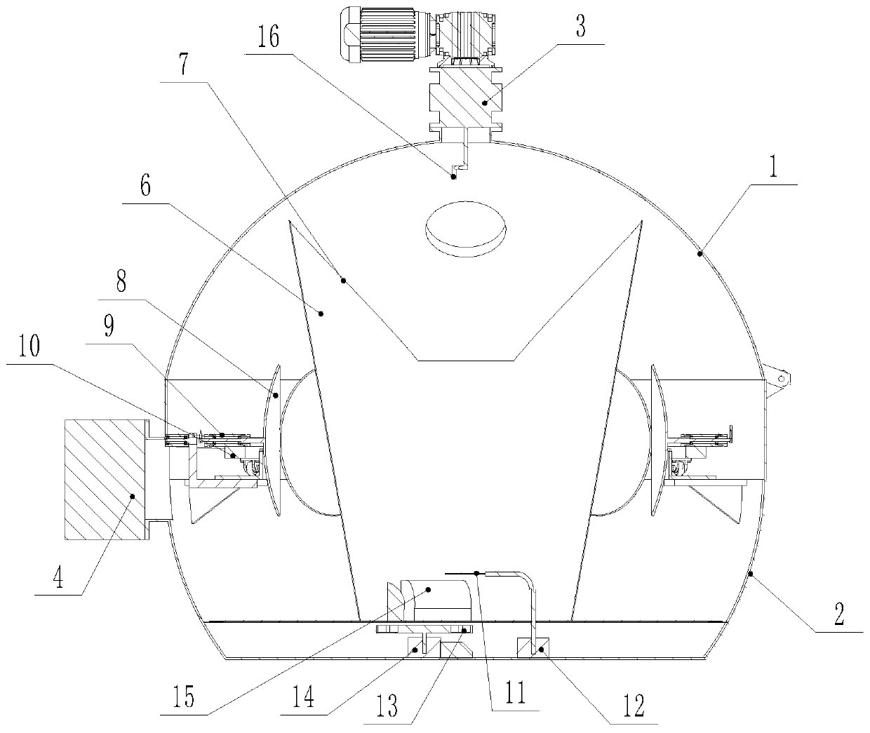
[0034] Such as Figure 1 to Figure 11 As shown, a revolving semiconductor evaporation table includes a lower casing 2 and an upper cover 1. The inner space between the lower casing 2 and the upper cover 1 forms an evaporation chamber, and the bottom of the evaporation chamber is provided with a The crucible 13, the bottom of the shell is provided with an electron beam generating device and a vacuum device for vacuuming the evaporation chamber. Since the electron beam generating device and the vacuum pumping device are conventional structures in the current evaporation table, their structure and principle are clear, so they will not be described in detail here.

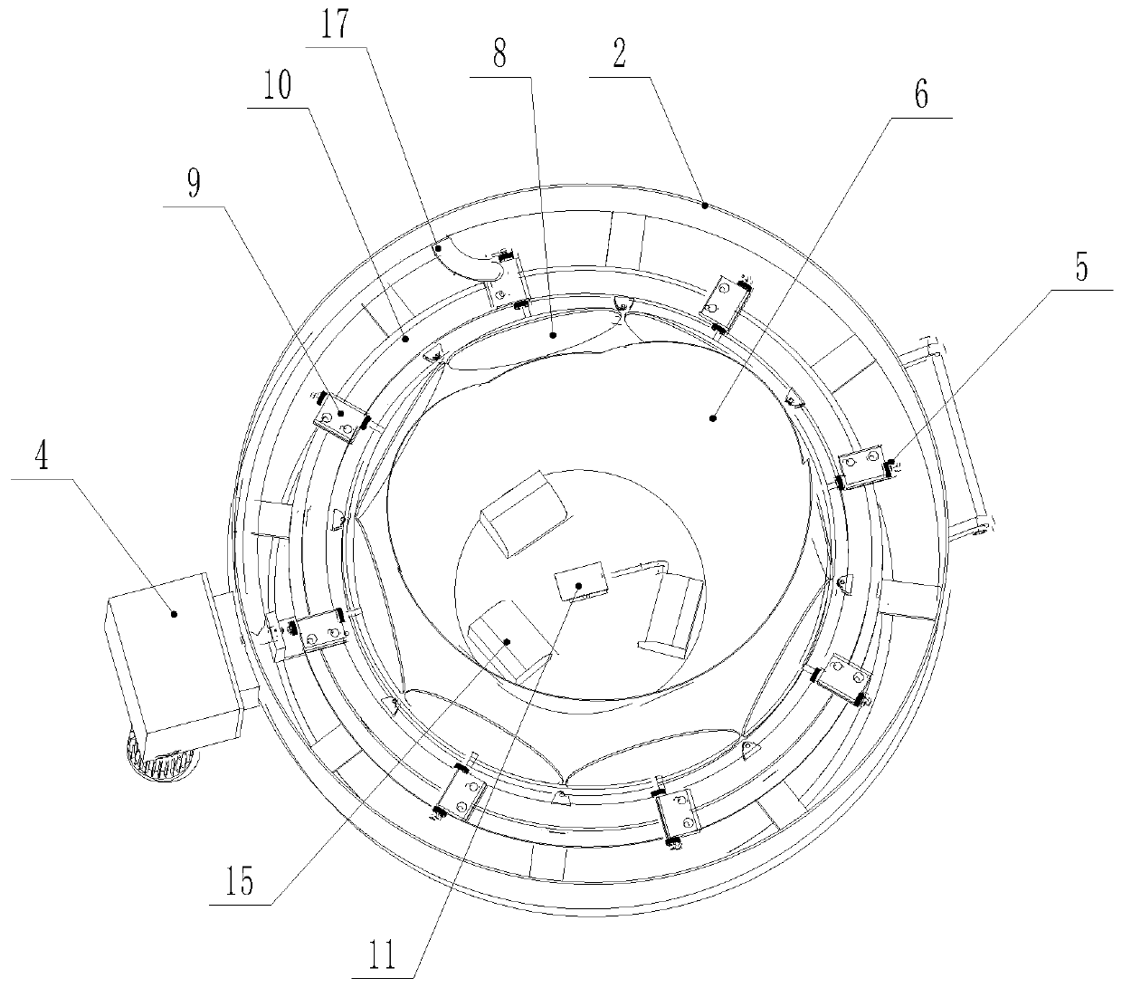
[0035] In this embodiment, the number of the crucibles 13 is multiple, preferably six, and the circumference of the multiple crucibles 13 is evenly distributed on the rotating support, and the rotating support is rotata...


PUM


Abstract

The invention discloses a revolution-type semiconductor evaporation table. The revolution-type semiconductor evaporation table comprises a lower shell body and an upper cover, wherein a rotary ring isrotationally installed on the inner wall of the lower shell body; the rotary ring is driven by a rotary power device; a plurality of slide glass covers are circumferentially and uniformly distributedon the rotary ring; a plurality of circular sheets are fixed to the working surface of each slide glass cover; each slide glass cover is rotationally installed on the fixed seat through a rotation shaft; the fixed seat is installed on the rotary ring through a self-locking structure; a material taking arm is rotationally installed in an inner cavity of the lower shell body; a self-locking switchover structure is arranged between a material taking end and the fixed seat; a deflection drive device is arranged on the lower shell body; a protection cover is arranged at the bottom of an evaporation cavity; each slide glass cover is located at the upper end of a protection cover and above a crucible while being located at an evaporation station; a rotation power device is arranged on the uppercover; and the rotation power device drives each slide glass cover at the evaporation station to rotate. The evaporation table is capable of ensuring the accuracy of an evaporation pattern, and higherin evaporation efficiency, so that a vacuumizing time is reduced.

Description

technical field [0001] The invention relates to an evaporation table, which belongs to the technical field of semiconductors, in particular to a revolving semiconductor evaporation table. Background technique [0002] Evaporation table is a commonly used semiconductor equipment, its main structure includes a lower shell and an upper cover, the inner space between the lower shell and the upper cover forms an evaporation chamber, the bottom of the evaporation chamber is provided with a crucible for placing metal, The bottom of the housing is provided with an electron beam generating device and a vacuum device for evacuating the evaporation chamber. A slide cover is provided in the evaporation chamber, and the slide cover is used to place semiconductor wafers. The principle is: first vacuumize the evaporation chamber to maintain a certain vacuum, place the metal in the crucible, and then the electron beam generating device generates a high-energy electron beam, and under the ac...

Claims


Application Information

Patent Timeline
Patent Type & Authority Applications(China)
IPC IPC(8): C23C14/30C23C14/56C23C14/50
CPCC23C14/243C23C14/30C23C14/505C23C14/564
Inventor 景苏鹏黄鹏飞刘卫平
Owner 苏州华楷微电子有限公司
Why Eureka
Try Eureka