Convenient-to-maintain and movable moisture removal device for electrical equipment

An electrical equipment and mobile technology, applied in the field of mobile dehumidification devices, can solve the problems of no air filtration function, inconvenient maintenance of equipment, single function, etc., achieve good dehumidification effect, improve convenience, and move fast. Effect

Inactive Publication Date: 2019-12-31
ZHENGZHOU INST OF TECH
View PDF5 Cites 0 Cited by
  • Summary
  • Abstract
  • Description
  • Claims
  • Application Information

AI Technical Summary

Problems solved by technology

[0002] If the electrical equipment is installed outdoors, if the seal is not tight, it will easily lead to high humidity and moisture in the equipment. The gas with high humidity will condense into water droplets when it meets the low temperature chassis shell, especially when the condensation is severe. Water droplets will be formed, which seriously threatens the safety of power grid equipment; it is usually necessary to remove moisture from electrical equipment; the moisture removal equipment in the prior art is inconvenient to move, has a single function when in use, and does not have the function of filtering air when inhaling air , the dehumidification effect is poor; when a fault occurs, the internal maintenance of the equipment is inconvenient, so it is necessary to design a mobile dehumidification device for electrical equipment that is easy to maintain

Method used


Image

  • Convenient-to-maintain and movable moisture removal device for electrical equipment
  • Convenient-to-maintain and movable moisture removal device for electrical equipment
  • Convenient-to-maintain and movable moisture removal device for electrical equipment

Examples


Embodiment Construction

[0018] The technical solutions of the present invention will be clearly and completely described below in conjunction with the embodiments. Apparently, the described embodiments are only some of the embodiments of the present invention, not all of them. Based on the embodiments of the present invention, all other embodiments obtained by persons of ordinary skill in the art without creative efforts fall within the protection scope of the present invention.

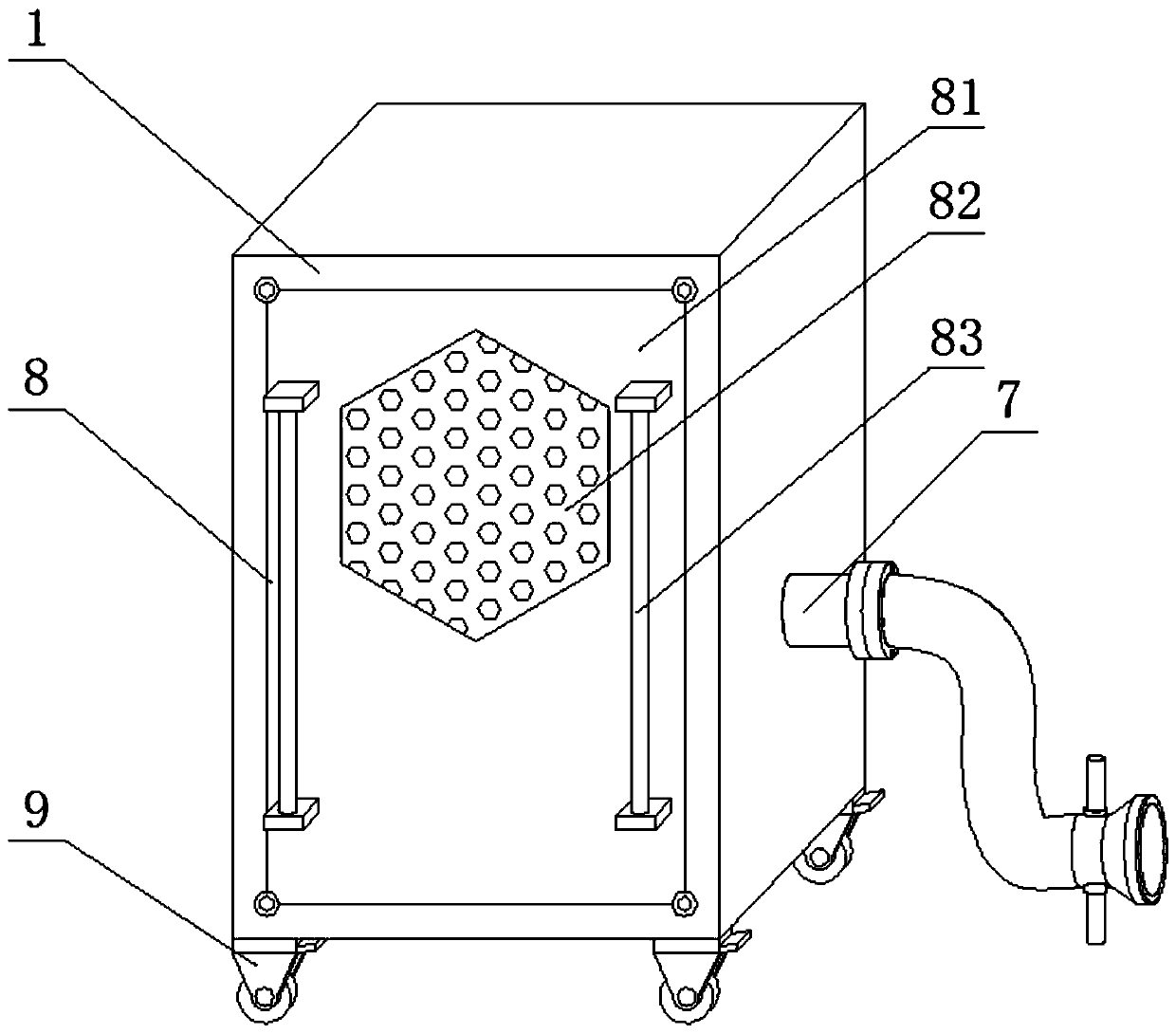
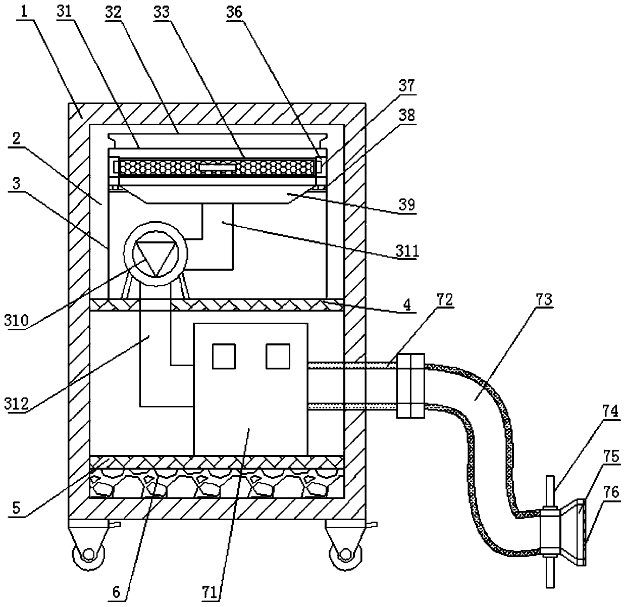
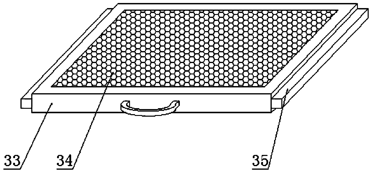
[0019] like Figure 1-3 As shown, a maintenance-friendly and mobile dehumidification device for electrical equipment includes an equipment box 1, a functional room 2, an air intake assembly 3, a first installation base plate 4, a second installation base plate 5, a buffer rubber plate 6, a drying Component 7, installation component 8 and universal wheel 9, universal wheel 9 is fixedly installed around the bottom end surface of equipment box 1 by welding, universal wheel 9 is universal self-locking wheel, easy to move; the i...


PUM


Abstract

The invention discloses a convenient-to-maintain and movable moisture removal device for electrical equipment. The device comprises an equipment box, a functional chamber, an air inlet assembly, a first mounting bottom plate, a second mounting bottom plate, a buffer rubber plate, a drying assembly, a mounting assembly and universal wheels. The functional chamber is formed in the equipment box, themounting assembly is arranged on the outer side of the functional chamber, the first mounting bottom plate is fixedly installed on the top of the inner side of the functional chamber through welding,the air inlet assembly is arranged at the top of the first mounting bottom plate, the second mounting bottom plate is fixedly installed on the bottom of the inner side of the functional chamber through welding, and the drying assembly is arranged on the top of the second mounting bottom plate. The convenient-to-maintain and movable moisture removal device for the electrical equipment is quick tomove. During use, air for drying is filtered, heated air is conveyed into the electrical equipment, and the moisture removal effect is good. Meanwhile, the interior of the equipment is convenient to maintain.

Description

technical field [0001] The invention relates to the field of moisture removal equipment, in particular to a maintenance-friendly and mobile moisture removal device for electrical equipment. Background technique [0002] If the electrical equipment is installed outdoors, if the seal is not tight, it will easily lead to high humidity and moisture in the equipment. The gas with high humidity will condense into water droplets when it meets the low temperature chassis shell, especially when the condensation is severe. Water droplets will be formed, which seriously threatens the safety of power grid equipment; it is usually necessary to remove moisture from electrical equipment; the moisture removal equipment in the prior art is inconvenient to move, has a single function when in use, and does not have the function of filtering air when inhaling air , the dehumidification effect is poor; when a fault occurs, the internal maintenance of the equipment is inconvenient. Therefore, it ...

Claims


Application Information

Patent Timeline
IPC IPC(8): F26B21/00H02B1/28B01D46/10B01D46/24B01D53/26
CPCB01D46/10B01D46/2418B01D53/26F26B21/001F26B21/003F26B21/004H02B1/28
Inventor 甄敬然时伟李红丽赵静雷钢
Owner ZHENGZHOU INST OF TECH
Why Eureka
Try Eureka