
Communication method and system for multi-antenna backscatter tags

A technology of backscattering and communication methods, applied in the field of communication methods and systems of multi-antenna backscattering tags, can solve the problems of large volume of antenna backscattering tags, avoid time synchronization problems, avoid space coupling problems, reduce Small size effect

Active Publication Date: 2021-04-20
HUAZHONG UNIV OF SCI & TECH
View PDF10 Cites 0 Cited by
  • Summary
  • Abstract
  • Description
  • Claims
  • Application Information

AI Technical Summary

Problems solved by technology

[0005] Aiming at the defects of the prior art, the object of the present invention is to propose a communication method and system for multi-antenna backscatter tags, aiming at solving the problem that the distance between required antennas is greater than that of radio frequency signals in existing communication methods based on multi-antenna technology. The problem of the large size of the antenna backscatter tag caused by the half-wavelength

Method used


Image

  • Communication method and system for multi-antenna backscatter tags
  • Communication method and system for multi-antenna backscatter tags
  • Communication method and system for multi-antenna backscatter tags

Examples


Embodiment 1

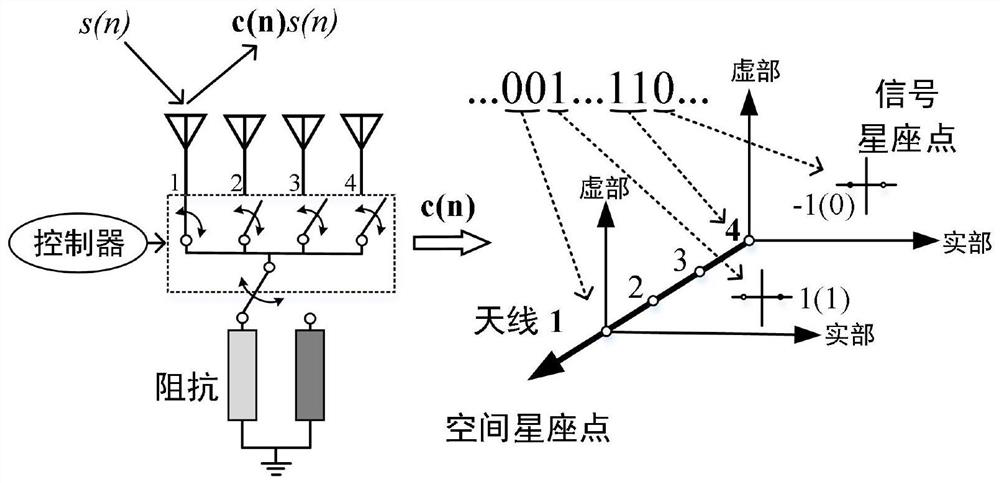
[0054] Taking the antenna number L of the multi-antenna tag as 4 as an example, as figure 2 A schematic diagram of space-backscatter joint modulation of multi-antenna tags is shown. As shown in the figure, when the tag information bit is "001", according to the formula log 2 (L) The number of bits of the calculated antenna index sequence is 2, the label modulation method is BPSK, and the label modulation order M mod is 2, according to the formula log 2 (M mod ) calculates that the number of bits in the transmission bit sequence is 1, so the antenna index sequence is "00", the transmission bit sequence is "1", and the antenna corresponding to the antenna index sequence of "00" is the first antenna in the multi-antenna tag , it means that the first antenna modulates and transmits the transmission bit sequence "1" using its corresponding label modulation method, that is, "00" is mapped to a space constellation point, and "1" is mapped to a signal constellation point. In time...

Embodiment 2

[0080] Taking the excitation source signal modulated by Quadrature Phase Shift Keying (QPSK) and the tag information modulated by Binary Phase Shift Keying (BPSK) as an example to analyze the performance of the detection system, it is worth noting that the The computational method can be extended to high-order modulation scenarios.

[0081] Specifically, because, in the process of joint signal detection, there is a coupling relationship between the signals received by the reader, and the excitation source signal and tag information have a strong correlation, the calculation reader of the communication system based on multi-antenna backscatter tags The method for increasing the respective bit error rates of the demodulated label information and the excitation source signal comprises the following steps:

[0082] (1) Given the estimated excitation source signal By calculating the label signal of the excitation source signal in both cases of correct estimation and error Bit e...


PUM


Abstract

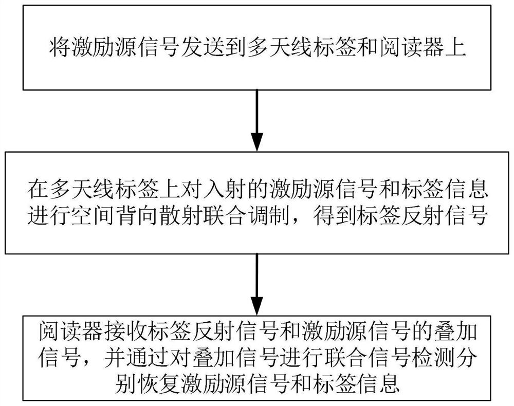
The invention discloses a communication method and system for multi-antenna backscatter tags. The method includes the following steps: S1, sending excitation source signals to multi-antenna tags and readers; S2, multi-antenna tags for incident excitation source signals Perform space-backscatter joint modulation with tag information to obtain tag reflection signals; S3. The reader receives the superimposed signal of the tag reflection signal and the excitation source signal, and recovers the excitation source signal and the excitation source signal respectively by performing joint signal detection on the superposition signal. Label Information. By performing space-backscatter joint modulation on the incident excitation source signal and tag information in the multi-antenna tag, one tag antenna in the multi-antenna tag is selected to work in each time slot according to the tag antenna index in the tag information, avoiding multiple There is spatial coupling between the tag antennas in the antenna tag, so that the distance between the antennas can be less than half the wavelength of the source signal, which reduces the size of the multi-antenna tag and greatly improves the communication performance.

Description

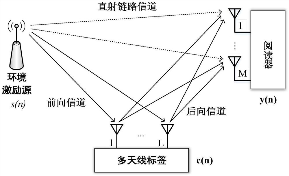
technical field [0001] The invention belongs to the field of multi-antenna and wireless communication, and more specifically relates to a communication method and system for a multi-antenna backscatter tag. Background technique [0002] Backscatter communication is a microwatt-level ultra-low power wireless communication technology. Among them, backscatter tags only use radio frequency signals in the environment, such as Wi-Fi signals, TV signals, etc. to complete information transmission, and do not require active radio frequency signal transmission, which is a passive communication process. Therefore, it is regarded by academia and industry as a key technology to achieve large-scale deployment of the Internet of Things. Compared with traditional radio frequency identification communication (Radio Frequency Identification, RFID), backscatter communication does not require a dedicated signal excitation source device, so it is easier to deploy. With the continuous developme...

Claims


Application Information

Patent Timeline
Patent Type & Authority Patents(China)
IPC IPC(8): H04B5/00H04B7/0413H04B7/22H04L27/20H04L27/22
CPCH04B5/0062H04B7/0413H04B7/22H04L27/20H04L27/22
Inventor 王巍牛志昂江涛
Owner HUAZHONG UNIV OF SCI & TECH
Learn More