Sleeve part clamping device and method

A clamping device and sleeve technology, applied in the field of sleeve parts clamping device, can solve problems such as inability to process qualified products, aggravate parts deformation, vibration, etc., and achieve increased rigidity, increased strength, and strong popularization. Effect

Inactive Publication Date: 2020-01-03
BEIJING HANGKE ENGINE CONTROL SYST SCI & TECH
View PDF11 Cites 1 Cited by
  • Summary
  • Abstract
  • Description
  • Claims
  • Application Information

AI Technical Summary

Problems solved by technology

Restricted by the structure, the wall thickness of the thinnest part is only 1.1mm. The fixture structure of the traditional machining center is mostly an end face compression structure, and one side is suspended in the air, which will cause deformation and vibration, and cannot process qualified products.
Because there is no angular positioning, more axial pressing force needs to be provided to ensure sufficient friction to prevent the parts from rotating, which aggravates the deformation of the parts

Method used


Image

  • Sleeve part clamping device and method
  • Sleeve part clamping device and method
  • Sleeve part clamping device and method

Examples


Embodiment Construction

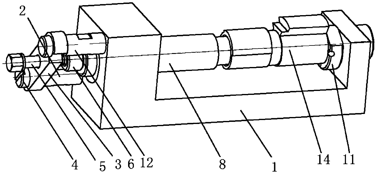
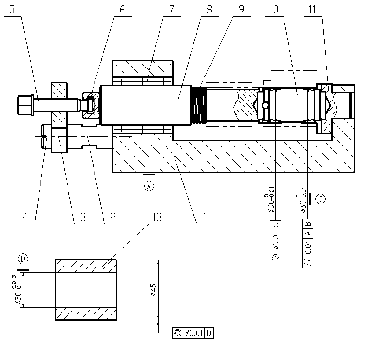
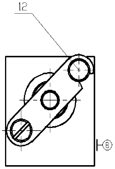
[0033] The present invention will be described in further detail below in conjunction with thin-walled parts of aero-engines (belonging to a kind of sleeve parts), see Figure 1-3 , in order to mill the thin-walled parts of the aero-engine, the clamping device for sleeve parts of the present invention is adopted, the device includes a base 1, a support 2, a rotary pressure plate 3, stepped screws 4, and small hexagonal head set screws 5, briquetting block 6, linear motion bearing 7, ejector rod 8, spring 9, biconical shaft 10, expansion shaft 11, support 2 12, watch part 13.

[0034] The base 1 is installed with support 1 2, support 2 12, linear motion bearing 7, ejector rod 8, expansion shaft 11, etc., to ensure that the ejector rod 8 has a high coaxiality requirement with the expansion shaft 11 in the moving state; Figure 4-5 As shown, one end of the ejector rod 8 and the expansion shaft 11 has an inner tapered hole and a "petal" structure, which can expand and contract; T...


PUM


Abstract

The invention belongs to the field of product tool design, and particularly relates to a sleeve part clamping device and method. Part deformation can be avoided while axial force is not applied. As for a traditional machining center fixture structure, more axial compression force needs to be provided because no angular positioning exists, and consequently deformation of parts is aggravated. According to the sleeve part clamping device, a base is provided with a left wall body and a right wall body, a jacking rod is slidably mounted on the left wall body, an expansion shaft is mounted on the right wall body, the opposite end faces of the jacking rod and the expansion shaft are provided with petal structures correspondingly, a double-cone shaft is mounted between the jacking rod and the expansion shaft, a sleeve part is mounted on the outer side of the double-cone shaft in a sleeving mode, and the jacking rod is of an integrated structure and is provided with different material partitions; when the jacking rod is jacked, the petal structures at the two ends expand to fix the sleeve part; and the device is further provided with a synchronizing piece, and the machining zero position isdetermined by pre-mounting the synchronizing piece. The problems that the thin-wall parts adopt end face compression, and consequently are prone to deforming, poor in rigidity and prone to vibratingare solved.

Description

technical field [0001] The invention belongs to the field of product tooling design, and in particular relates to a clamping device and method for sleeve-like parts, which can avoid deformation of the parts while applying no axial force. Background technique [0002] The three-dimensional cam is an important part of the aero-engine, which is used to control the accurate position of other parts, so it has high precision and high stability to the machining process. The three-dimensional cam for a certain type of aero-engine is in the shape of a cylinder, see appendix figure 1 , the two ends are three-dimensional cam surface and spline respectively, and the three-dimensional cam part needs to be processed by machining center. Restricted by the structure, the wall thickness of the thinnest part is only 1.1mm. The fixture structure of the traditional machining center is mostly an end face compression structure, and one side is suspended in the air, which will cause deformation a...

Claims


Application Information

Patent Timeline
Patent Type & Authority Applications(China)
IPC IPC(8): B23Q3/06
CPCB23Q3/065
Inventor 王兆起张耀王辉刘长兴
Owner BEIJING HANGKE ENGINE CONTROL SYST SCI & TECH
Why Eureka
Try Eureka