Fixed building reinforcement cutting machine

A technology for building steel bars and cutting machines, which is applied in the directions of grinding machine parts, grinding workpiece supports, grinding machines, etc., can solve the problems of labor and injury of construction workers, and achieve the effect of high safety and prolonging service life.

Active Publication Date: 2020-01-03
安徽煌宇建设有限公司
View PDF8 Cites 4 Cited by
  • Summary
  • Abstract
  • Description
  • Claims
  • Application Information

AI Technical Summary

Problems solved by technology

[0005] In order to overcome the disadvantages of greater vibration generated by the cutting of steel bars, which will cause more labor for construction workers and may cause serious injuries to construction workers, the technical problem to be solved is: to provide a relatively labor-saving and high-safety fixed construction steel bar Cutting Machine

Method used


Image

  • Fixed building reinforcement cutting machine
  • Fixed building reinforcement cutting machine
  • Fixed building reinforcement cutting machine

Examples


Embodiment approach 1

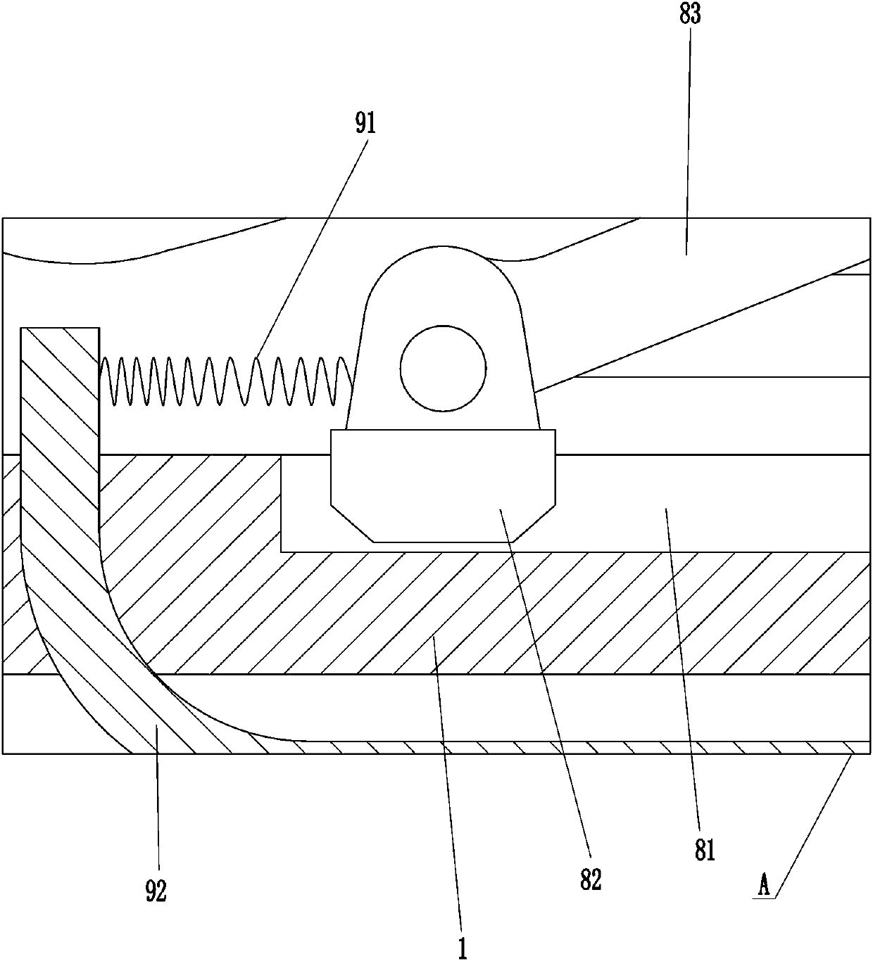
[0027] A kind of fixed building reinforcement cutting machine, refer to figure 1 and Figure 6 , including a mounting frame 1, an arc beam 2, a first handle 3, a second handle 6, a cutting device 8 and a fixing device 9, the left side of the mounting frame 1 is connected with an arc beam 2, and the left part of the arc beam 2 is fixedly connected There is a first handle 3, a second handle 6 is connected to the rear side of the mounting frame 1, a cutting device 8 is provided on the top of the mounting frame 1, and the cutting device 8 is used to cut steel bars, and a fixing device 9 is provided at the bottom of the mounting frame 1. 9 is used for clamping reinforcing bar.

[0028] refer to figure 1 , Figure 8 and Figure 9 , also includes a control module, a pause key 4 and a start key 5, the top of the arc-shaped beam 2 is provided with a pause key 4, and the front side of the arc-shaped beam 2 is provided with a start key 5, and both the pause key 4 and the start key 5 ...

Embodiment approach 2

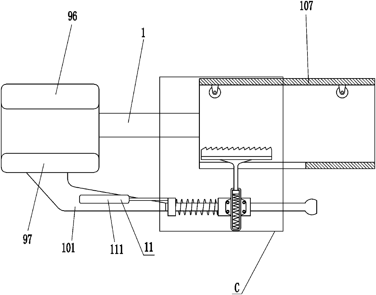
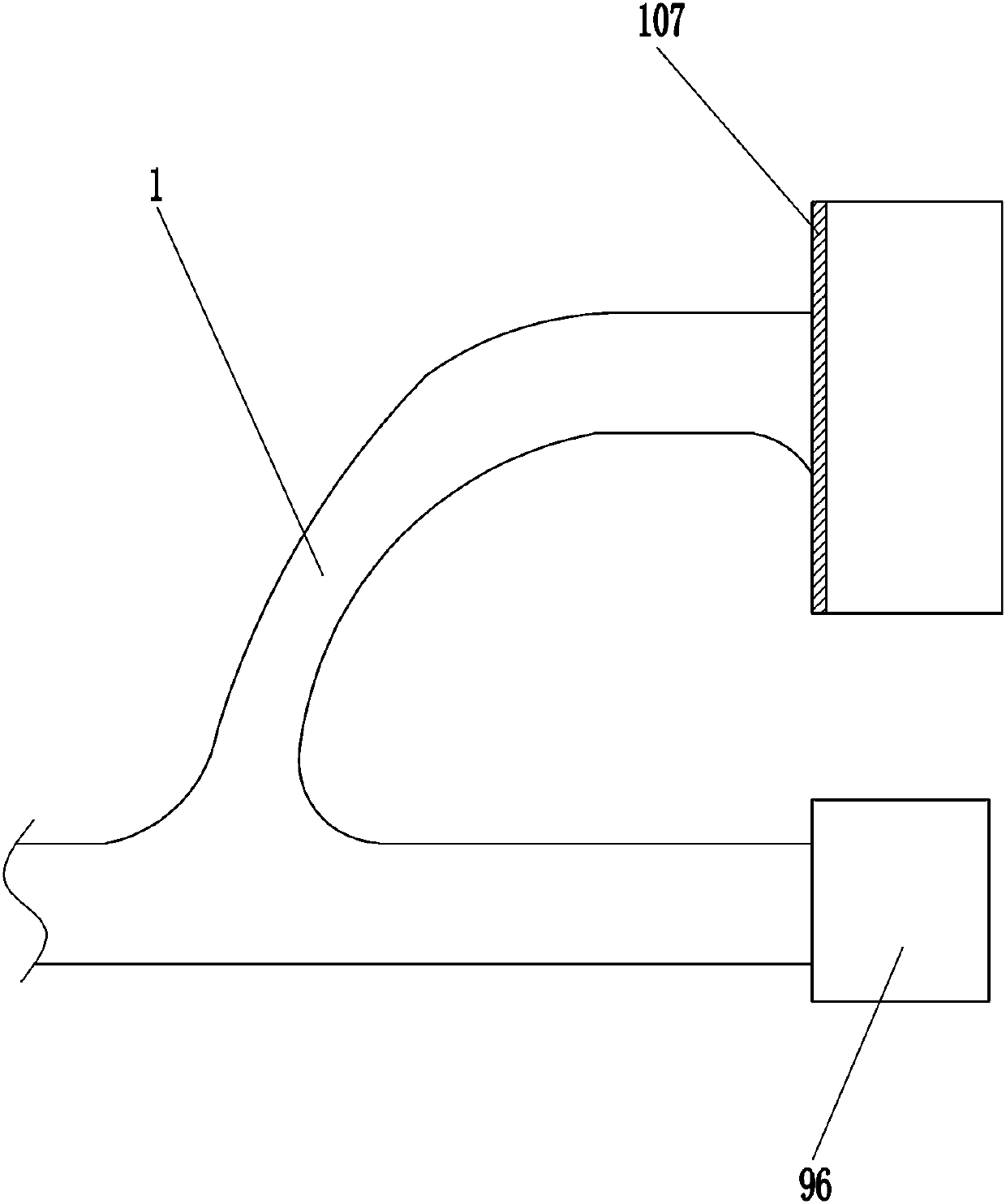
[0035] On the basis of Embodiment 1, refer to Figure 4 , Figure 5 and Figure 7 , also includes an anti-drop device 10, the anti-drop device 10 includes a fixed plate 101, a slide bar 102, a first sliding sleeve 103, a sleeve 104, a second spring 105, a friction plate 106, a gap ring 107 and a sleeve Rod 108, notch ring 107 is installed on the right side of mounting frame 1, and notch ring 107 is positioned at the rear side of first pressing plate 96, and the bottom of second pressing plate 97 is connected with fixed plate 101, and the rear side of fixed plate 101 is equipped with the slide that plays guiding role. Rod 102, fixed plate 101 is connected with slide bar 102 by the mode of bolt connection, slide bar 102 is provided with the first sliding sleeve 103, and sleeve 104 is installed on the first sliding sleeve 103, and first sliding sleeve 103 is passed through bolt The connection mode is connected with the sleeve 104, the sleeve 104 is provided with a sleeve rod 10...


PUM


Abstract

The invention relates to a reinforcement cutting machine, in particular to a fixed building reinforcement cutting machine. The technical problem to be solved is how to provide the fixed building reinforcement cutting machine with more power saving and high safety. The fixed building reinforcement cutting machine comprises a mounting frame, an arc beam, a first handle, a second handle and the like;the left side of the mounting frame is connected with the arc beam; the left part of the arc beam is fixedly connected with the first handle; and the back side of the mounting frame is connected withthe second handle. Reinforcements can be clamped through a fixing device, so that building workers can save more power, and the safety is high; through an anti-falling device, the reinforcements canbe prevented from falling after cutting, so that the reinforcements can be prevented from smashing other persons or objects; through a reinforcement deviation device, the friction between the reinforcements and a grinding wheel can be prevented, so that the service life of the grinding wheel can be prolonged; and through a protecting device, the building workers can be prevented from touching thegrinding wheel.

Description

technical field [0001] The invention relates to a steel bar cutting machine, in particular to a fixed building steel bar cutting machine. Background technique [0002] Steel bars include smooth round steel bars, ribbed steel bars, twisted steel bars, etc. Steel bars can be used in the construction industry to make buildings more stable. After the building is poured, some steel bars will be exposed outside. In order not to affect the subsequent construction, the redundant truncated steel bars. [0003] At present, construction workers usually use steel bar cutters to cut steel bars, but the steel bar cutting machine will generate large vibrations, which will cause construction workers to work harder. In addition, a slight movement of the construction workers' hands may cause damage to the equipment, which may be serious. Injury to construction workers. [0004] Therefore, it is necessary to design a device that is relatively labor-saving and safe. Contents of the inventio...

Claims


Application Information

Patent Timeline
Patent Type & Authority Applications(China)
IPC IPC(8): B24B27/08B24B41/06B24B55/10B24B41/00B24B55/00
CPCB24B27/08B24B41/007B24B41/067B24B55/00B24B55/102
Inventor 不公告发明人
Owner 安徽煌宇建设有限公司
Why Eureka
Try Eureka