

Coordinate system calibration and positioning method, system and equipment of robot and medium
A calibration method and positioning method technology, applied in the direction of manipulators, program-controlled manipulators, manufacturing tools, etc., can solve the problems of insufficient absolute positioning calibration accuracy and complicated calibration process
- Summary
- Abstract
- Description
- Claims
- Application Information
AI Technical Summary
Problems solved by technology
Method used
Image

Examples
Embodiment 1
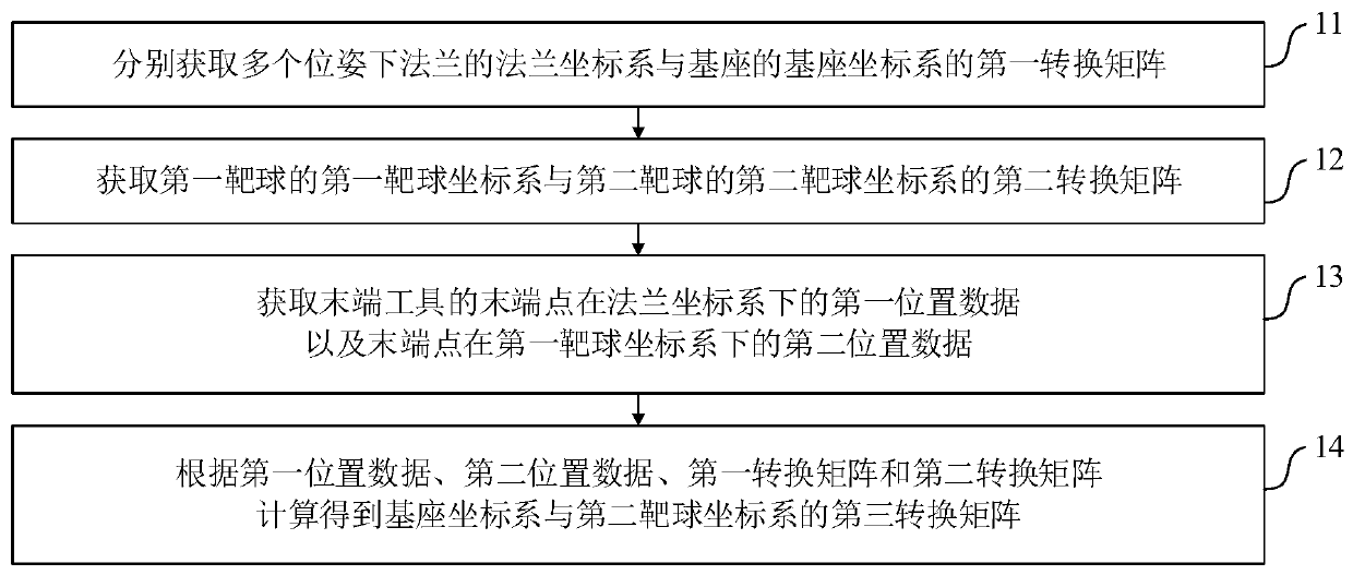
[0066] A method for calibrating the coordinate system of a robot, such as figure 1 As shown, the flange at the end of the mechanical arm of the robot is provided with an end tool, and a first target ball and a second target ball are respectively set on the base of the end tool and the robot. The coordinate system calibration method include:
[0067] Step 11. Obtain the first transformation matrix of the flange coordinate system of the flange and the base coordinate system of the base in multiple poses respectively; it should be noted that the first transformation matrix can be directly read from the robot system , and it changes with different poses of the manipulator.
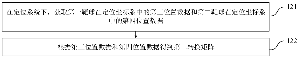
[0068] Step 12, obtaining a second transformation matrix of the first target ball coordinate system of the first target ball and the second target ball coordinate system of the second target ball;
[0069] Step 13. Obtain the first position data of the end point of the end tool in the flange coordinate syste...
Embodiment 2
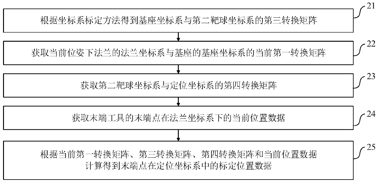
[0079] A positioning method for a robot, such as image 3 As shown, the positioning method is realized by using the coordinate system calibration method of the robot as described in Embodiment 1, which specifically includes:
[0080] Step 21. Obtain the third transformation matrix between the base coordinate system and the second target ball coordinate system according to the coordinate system calibration method;
[0081] Step 22. Obtain the current first transformation matrix of the flange coordinate system of the flange and the base coordinate system of the base under the current pose;
[0082] Step 23, obtaining the fourth transformation matrix of the second target ball coordinate system and the positioning coordinate system;
[0083] Step 24, obtain the current position data of the end point of the end tool in the flange coordinate system; it should be noted that once the end tool is set, the current position data is a fixed value, which can be obtained by the robot itsel...
Embodiment 3
[0094] A robot coordinate system calibration system, such as Figure 5 As shown, the flange at the end of the mechanical arm of the robot is provided with an end tool, and a first target ball and a second target ball are respectively set on the base of the end tool and the robot, and the coordinate system calibration system Including a first conversion matrix acquisition module 1, a second conversion matrix acquisition module 2, a position data acquisition module 3 and a third conversion matrix calculation module 4;
[0095] The first transformation matrix acquisition module 1 is used to respectively acquire the first transformation matrices of the flange coordinate system of the flange and the base coordinate system of the base in multiple poses; it should be noted that the first The transformation matrix can be read directly from the robot system, and it changes with different poses of the manipulator.
[0096] The second transformation matrix acquisition module 2 is used t...
PUM
 Abstract
Description
Claims
Application Information