Exhaust butterfly valve

A technology of exhaust butterfly valve and exhaust pipe, which is applied in the direction of lifting valve, valve details, valve device, etc., can solve the problem of damaged valve, achieve the effect of preventing water hammer, saving cost and preventing damage

Pending Publication Date: 2020-01-03
大禹节水(天津)有限公司
View PDF0 Cites 2 Cited by
  • Summary
  • Abstract
  • Description
  • Claims
  • Application Information

AI Technical Summary

Problems solved by technology

[0003] Butterfly valves currently on the market are only used for drainage. During the drainage process, the valves are often damaged due to water hammer and cavitation in the pipeline. At present, there is an urgent need for a dual-purpose valve for exhaust and water control.

Method used


Image

  • Exhaust butterfly valve

Examples


Embodiment Construction

[0018] The present invention will be further described in detail through the accompanying drawings and specific embodiments below.

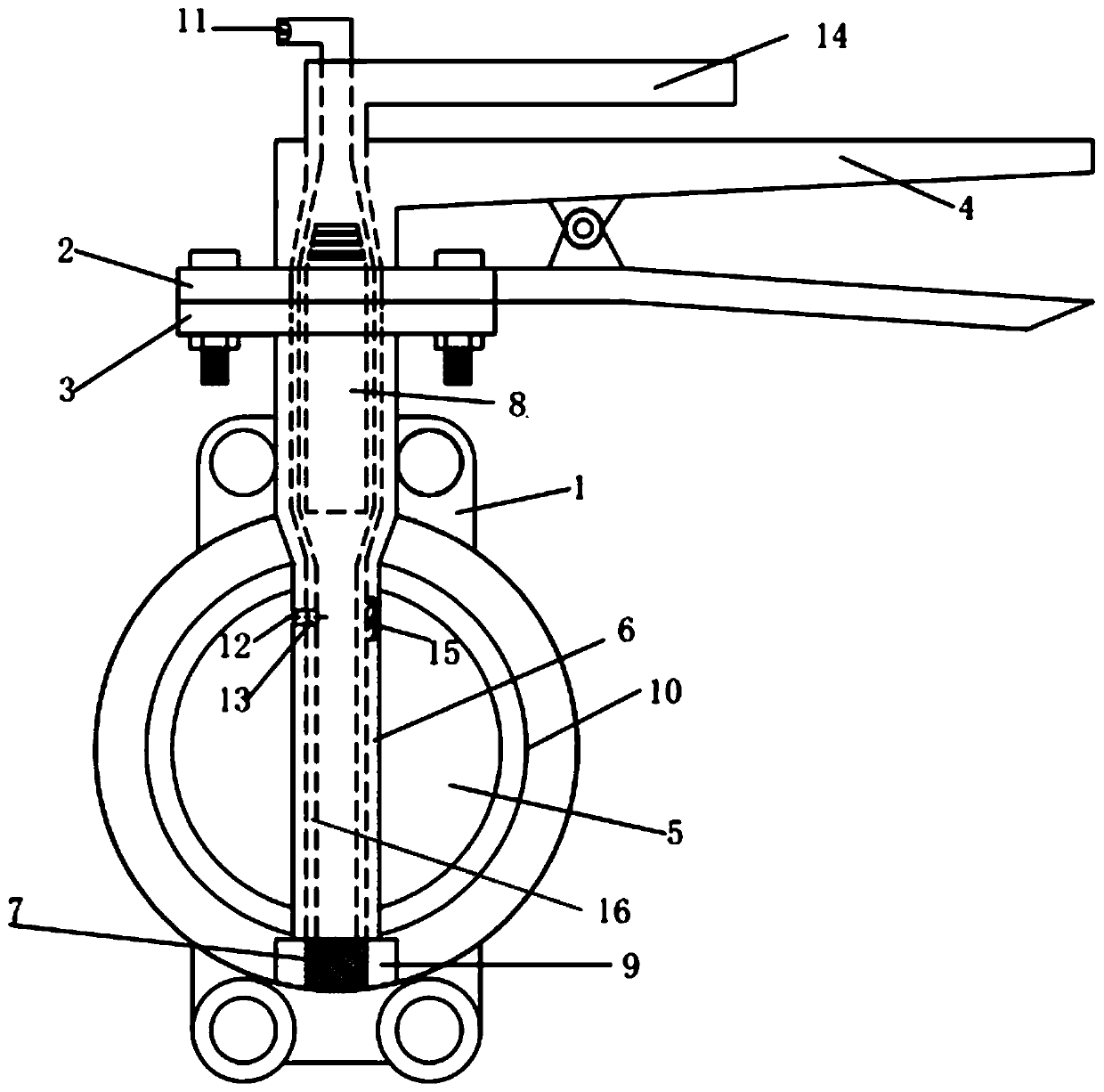
[0019] Such as figure 1 As shown, an exhaust butterfly valve includes a valve body 1 and a water sealing valve 5 arranged in the valve body. A sealing rubber ring 10 is connected to the water sealing valve 5. It is characterized in that a valve handle is connected above the valve body 1 4 and the first fixed plate 2 and the second fixed plate 3 that fix the valve handle 4, the valve handle 4 is embedded with an exhaust handle 14, the valve handle 4 is connected with the water sealing valve through a hollow tube 6, and by turning the valve handle 4 To control the rotation of the sealing water valve 5 so as to achieve the purpose of controlling the waterway; the exhaust handle is connected with the exhaust pipe 16, and the exhaust pipe 16 is nested in the hollow pipe 6, and the exhaust pipe 16 can rotate in the hollow pipe 6 , on the pipe wall of ...


PUM


Abstract

The invention discloses an exhaust butterfly valve. The exhaust butterfly valve comprises a valve body and a water-sealing valve arranged in the valve body. A sealing rubber ring is connected to the water-sealing valve. A valve handle, a first fixing plate and a second fixing plate are connected above the valve body, wherein the valve handle is fixed by the first fixing plate and the second fixingplate. An exhaust handle is embedded in the valve handle. The valve handle is connected with the water-sealing valve through a hollow pipe. Rotation of the water-sealing valve is controlled through rotating the valve handle, and thus the purpose of controlling the water route can be achieved. The exhaust handle is connected with an exhaust pipe. The exhaust pipe is nested in the hollow pipe. Theexhaust pipe can rotate in the hollow pipe. An external exhaust hole and an internal exhaust hole which are matched with each other are formed respectively in the portions, close to the top of the inner wall of the valve body, in the pipe walls of the hollow pipe and the exhaust pipe. An exhaust port communicating with the internal cavity of the exhaust pipe is formed in the top of the exhaust handle. The exhaust butterfly valve has the following advantages that the phenomenon of water hammer can be effectively prevented from occurring in a pipeline, and damage to the pipeline and the valve isprevented; and the cost is lowered, and there is no need for installing other exhaust devices additionally.

Description

technical field [0001] The invention relates to the field of industrial pipeline valves, in particular to an exhaust butterfly valve. Background technique [0002] In my country's agricultural irrigation, due to the length of the drainage pipe, a special exhaust valve is also equipped when the valve is assembled, which greatly increases the economic cost. [0003] Butterfly valves currently on the market are only used for drainage. During the drainage process, the valves are often damaged due to water hammer and cavitation in the pipeline. At present, there is an urgent need for a dual-purpose valve for exhaust and water control. Contents of the invention [0004] The object of the present invention is to overcome the defects in the prior art and provide an exhaust butterfly valve capable of discharging gas in the pipeline. [0005] In order to achieve the above object, the technical scheme of the present invention is as follows: [0006] An exhaust butterfly valve, incl...

Claims


Application Information

Patent Timeline
Patent Type & Authority Applications(China)
IPC IPC(8): F16K1/22F16K1/32F16K31/60
CPCF16K1/22F16K1/32F16K31/60
Inventor 王浩宇田玉龙纪学伟俞晓会王强学
Owner 大禹节水(天津)有限公司
Why Eureka
Try Eureka