Device and method for measuring temperature rise efficiency of low-state compression component

A technology of state compression and efficiency measurement, which is applied in the direction of measurement devices, machine/structural component testing, heat measurement, etc. It can solve the problems of large error in temperature measurement results, affecting the accuracy of temperature rise efficiency, lack of accurate and effective measurement methods, etc. , to achieve the effect of reducing heat conduction error, improving accuracy and reducing measurement uncertainty

Inactive Publication Date: 2020-01-03
BEIJING CHANGCHENG INST OF METROLOGY & MEASUREMENT AVIATION IND CORP OF CHINA
View PDF4 Cites 0 Cited by
  • Summary
  • Abstract
  • Description
  • Claims
  • Application Information

AI Technical Summary

Problems solved by technology

Due to the existence of various errors such as static graduation error, speed error, and heat conduction error of the temperature sensor sensitive element, the error of the temperature measurement result is large, which in turn affects the accuracy of the temperature rise efficiency, so that the key performance parameters of the engine compression components cannot be obtained accurately. evaluation of
In the fields of aero engines, gas turbines, etc., the requirements for the measurement accuracy of key performance parameters of components are getting higher and higher, but for the temperature rise efficiency of compression components under low conditions, there is still a lack of accurate and effective measurement methods

Method used


Image

  • Device and method for measuring temperature rise efficiency of low-state compression component
  • Device and method for measuring temperature rise efficiency of low-state compression component
  • Device and method for measuring temperature rise efficiency of low-state compression component

Examples


Embodiment 1

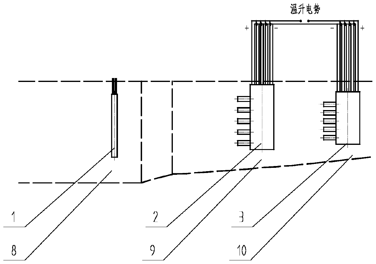
[0042] Such as figure 1 As shown, a low-state compression part temperature rise efficiency measurement device disclosed in this embodiment, a voltage regulator box 8 platinum resistance temperature sensor 1, a compression part inlet temperature sensor 2, a compression part outlet temperature sensor 3, a thick wire 4, a thin wire 5. The shielding cover 6 and the sensor housing 7 . For the convenience of description, the compression part inlet temperature sensor 2 and the compression part outlet temperature sensor 3 are collectively referred to as temperature sensors, that is, the temperature sensor is the compression part inlet temperature sensor 2 or the compression part outlet temperature sensor 3, and the names are determined according to the layout of the inlet or outlet measurement section.

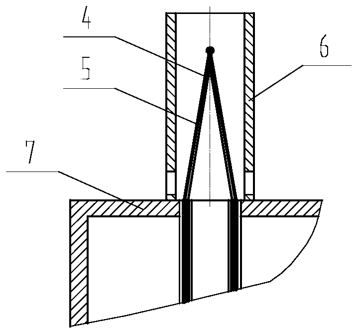
[0043] Such as figure 2 As shown, both the inlet temperature sensor 2 and the outlet temperature sensor 3 of the compression part adopt a double-wire multi-point single-shielding st...


PUM

PropertyMeasurementUnit
diameteraaaaaaaaaa
diameteraaaaaaaaaa
diameteraaaaaaaaaa

Abstract

The invention discloses a device and a method for measuring the temperature rise efficiency of a low-state compression component, and belongs to the field of measurement of key performance parametersof engine components. The device comprises a voltage stabilizing box platinum resistance temperature sensor, an inlet temperature sensor, an outlet temperature sensor, thick wires, thin wires, a shielding cover and a sensor shell. The inlet temperature sensor and the outlet temperature sensor adopt double-wire multi-point single-shielding structures, and static errors of thermocouple wires are reduced through dense distribution of the temperature sensors; meanwhile, double-wire epitaxy is adopted, so that the heat conduction error of the temperature sensors is reduced, and the accuracy of a temperature measurement result is improved; corresponding measuring points of the inlet temperature sensor and the outlet temperature sensor adopt the thermocouple wires manufactured in the same batch,and different measuring points adopt the thermocouple wires manufactured in different batches, so that the measurement results of different measuring points are free of correlation caused by the thermocouple wires, and the measurement uncertainty is reduced; and the measurement uncertainty of temperature rise efficiency can be reduced by adopting the methods such as reverse cascade and thermo wiredecorrelation between measuring points.

Description

technical field [0001] The invention relates to a device and method for measuring key performance parameters of engine components, in particular to a device and method for measuring the temperature rise efficiency of engine compression components in a low state, and belongs to the field of measuring key performance parameters of engine components. Background technique [0002] At present, the temperature rise efficiency of the compression parts of the engine in the low state is measured by the sub-measurement method, that is, a temperature sensor is arranged at the inlet of the surge tank or the compression part to measure the inlet temperature, and a temperature sensor is arranged at the outlet of the compression part to measure the outlet temperature. Due to the existence of various errors such as static graduation error, speed error, and heat conduction error of the temperature sensor sensitive element, the error of the temperature measurement result is large, which in tur...

Claims


Application Information

Patent Timeline
Patent Type & Authority Applications(China)
IPC IPC(8): G01M15/04G01K7/18G01K7/02
CPCG01M15/048G01K7/18G01K7/02
Inventor 赵俭
Owner BEIJING CHANGCHENG INST OF METROLOGY & MEASUREMENT AVIATION IND CORP OF CHINA
Why Eureka
Try Eureka