Method for braking a vehicle, and drive train of a vehicle

A technology for braking vehicles and drive trains, applied in braking control systems, braking system interactions, brakes, etc., can solve the problems of expensive manufacturing and cost-effective transmission design structure.

Pending Publication Date: 2020-01-03
SCHAEFFLER TECH AG & CO KG
View PDF7 Cites 0 Cited by
  • Summary
  • Abstract
  • Description
  • Claims
  • Application Information

AI Technical Summary

Problems solved by technology

[0004] The disadvantage here is that a transmission with an integrated transmissi

Method used


Image

  • Method for braking a vehicle, and drive train of a vehicle

Examples


Embodiment Construction

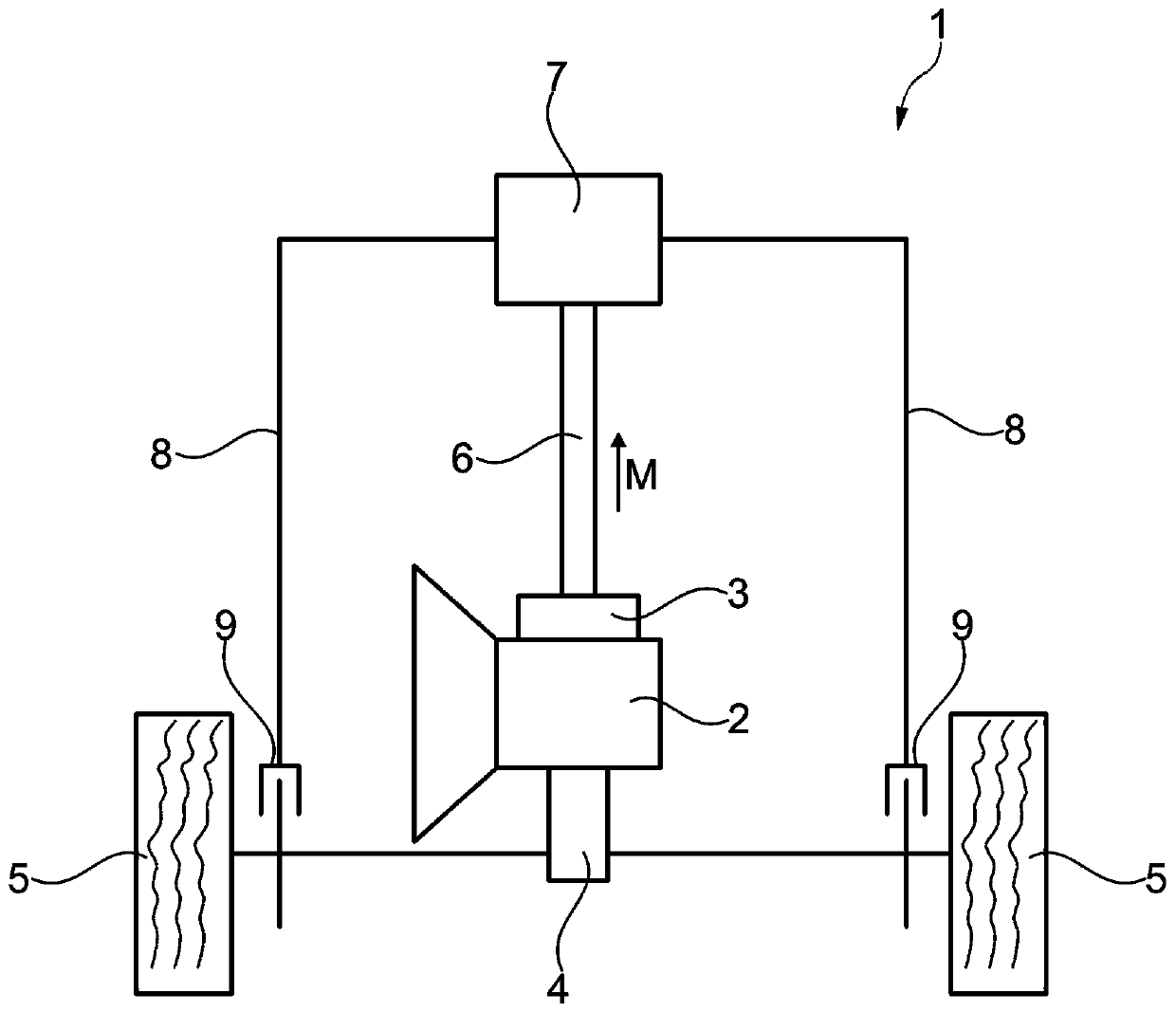
[0018] figure 1 An exemplary embodiment of a drive train 1 according to the invention of a vehicle is shown in , wherein the transmission 2 is actuated by a transmission control device 3 . The transmission 2 is connected here via a differential 4 to the wheels 5 . The transmission control unit 3 is connected to a brake control unit 7 , for example an ABS control unit, via a data bus 6 , for example a CAN bus. A brake control device 7 of a brake actuator (not further shown) is coupled via a corresponding hydraulic line 8 to a wheel brake 9 located opposite a wheel 5 .

[0019] If a fault occurs in the transmission 2 (this fault in a dual clutch transmission may, for example, be that a gear cannot be disengaged on a subtransmission of the dual clutch transmission), the vehicle will roll further and more and more fast, which without brake intervention would lead to the risk of an accident. This fault is detected by the transmission control unit 3 . In this case, the transmiss...


PUM


Abstract

The invention relates to a method for braking a vehicle, the vehicle having a transmission (2) controlled by a transmission control unit (3). In a method in which a transmission brake is not required,the transmission control unit (3) electronically requests a braking intervention.

Description

technical field [0001] The invention relates to a method for braking a vehicle, the vehicle having a transmission actuated by a transmission control device, and also to a drive train of the vehicle. Background technique [0002] A dual clutch transmission is known from DE 103 10 471 A1, wherein a transmission brake is assigned to each subsystem within the transmission, so that each input shaft has its own gear placed in the highest gear and brake between the lowest gears. [0003] DE 10 2009 021 894 B1 discloses a method for controlling a drive train of a motor vehicle, in which braking is performed by means of an automatically actuated braking system in the event of a transmission failure. The brakes used for this purpose are designed as transmission brakes. [0004] The disadvantage here is that a transmission with an integrated transmission brake is very complex in design and therefore also very expensive in production. Contents of the invention [0005] The object o...

Claims


Application Information

Patent Timeline
IPC IPC(8): B60W50/029B60T8/1755
CPCB60W50/029B60T8/1755B60T2260/04B60T2270/402B60T2270/10B60T2270/30B60T2270/20B60T7/12B60T8/17B60W10/18B60W30/00B60W10/10
Inventor 约翰尼斯·拉默斯
Owner SCHAEFFLER TECH AG & CO KG
Why Eureka
Try Eureka