Heat preservation method and system for stirring barrels in frit channels

A technology for mixing barrels and glass frit, applied in glass production, glass furnace equipment, glass manufacturing equipment, etc., can solve problems such as enlarged gaps, increased volatiles, and bubbles in glass substrates

Inactive Publication Date: 2020-01-07
ZHENGZHOU XUFEI OPTOELECTRONICS TECH +1
View PDF5 Cites 1 Cited by
  • Summary
  • Abstract
  • Description
  • Claims
  • Application Information

AI Technical Summary

Problems solved by technology

In this way, the upper end of the expanded mixing tank is not on the same level as the flange, which makes the cover plate tilt, resulting in a larger gap between the cover plates, faster heat loss, and poor insulation effect of the mixing tank.
If the temperature on the upper part of the cover plate is low, the volatiles in the upper part of the mixing tank will increase abnormally, and the volatiles will fall into the mixing tank when they grow to a certain extent, causing defects such as bubbles on the glass substrate, which will affect the yield of the production line.

Method used


Image

  • Heat preservation method and system for stirring barrels in frit channels
  • Heat preservation method and system for stirring barrels in frit channels
  • Heat preservation method and system for stirring barrels in frit channels

Examples


Embodiment Construction

[0032] Specific embodiments of the present disclosure will be described in detail below in conjunction with the accompanying drawings. It should be understood that the specific embodiments described here are only used to illustrate and explain the present disclosure, and are not intended to limit the present disclosure.

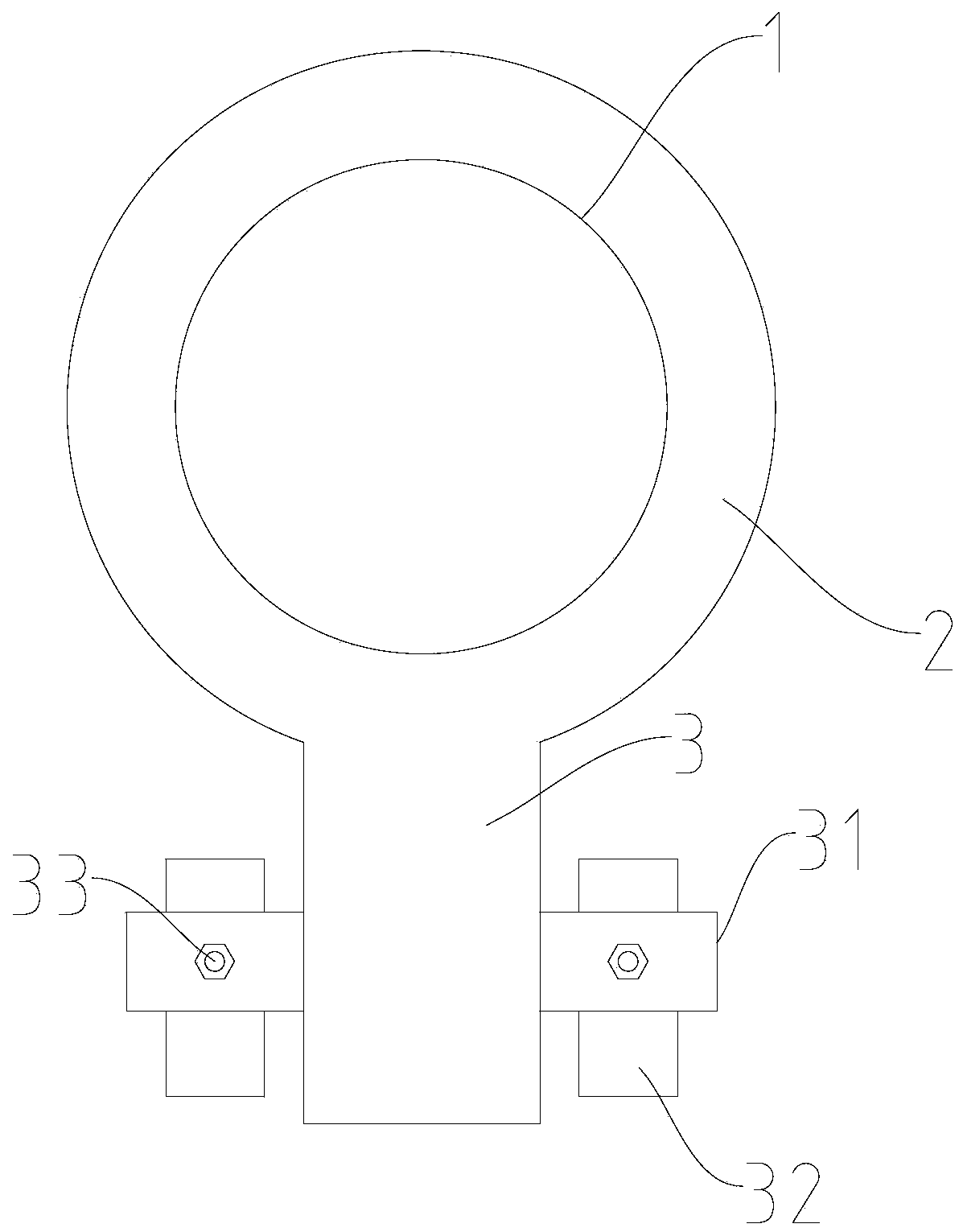
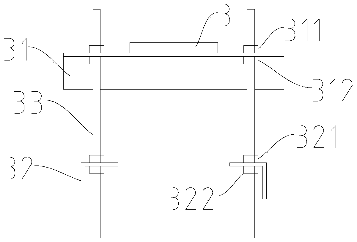
[0033] In this disclosure, unless otherwise specified, the used orientation words such as "up" and "down" are defined according to usage habits. Specifically, refer to image 3 and Figure 4 The direction of the drawing, "inner" and "outer" refer to the outline of the corresponding component itself, and "first" and "second" used in this disclosure are to distinguish one element from another element, not sequence and importance. When the following description refers to the accompanying drawings, the same reference numerals in different drawings represent the same or similar elements unless otherwise indicated.

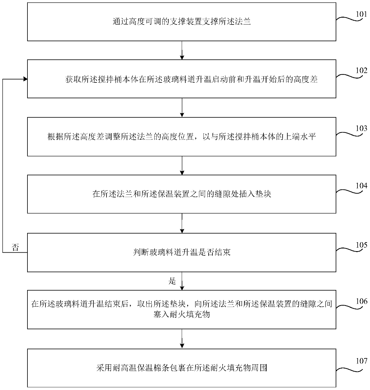
[0034] like Figure 1 to Figure 5 As shown, ...


PUM

PropertyMeasurementUnit
lengthaaaaaaaaaa

Abstract

The invention relates to a heat preservation method and a heat preservation system for stirring barrels in frit channels. A stirring barrel comprises a stirring barrel body and a flange which is formed at the upper end of the stirring barrel body and horizontally flanged outwards, the periphery of the stirring barrel body is coated with a heat preservation device, the flange is horizontally connected with a copper bar used for electric conduction, and the heat preservation method comprises the steps that: supporting the flange through a height-adjustable supporting device; obtaining the heightdifference of the stirring barrel body before and after the temperature rise starting of a frit channel; adjusting the height position of the flange according to the height difference so that the flange is horizontal with the upper end of the stirring barrel body; inserting a cushion block into a gap between the flange and a heat preservation device; and after temperature rising of the frit channel, taking the cushion block out, and filling a refractory filler into a gap between the flange and the heat preservation device; after the frit channel is heated and opened, adjusting the height of the supporting device until the height of the flange is consistent with that of the upper end of the stirring barrel body, so that heat loss in the stirring barrel due to inclination of a cover plate can be reduced, and then the qualified product yield of glass substrates is increased.

Description

technical field [0001] The present disclosure relates to the field of manufacturing liquid crystal glass substrates, in particular to a heat preservation method and a heat preservation system for a mixing barrel in a glass channel. Background technique [0002] In the production process of liquid crystal glass substrates, the glass forehearth is used for material homogenization, clarification and cooling of molten glass, and the mixing barrel in the glass forehearth is an important mechanism for homogenizing the glass liquid. In production, in order to ensure the temperature of the mixing tank, a pair of cover plates are usually arranged on the upper flange of the mixing tank. After the glass feeder is heated up and started, the mixing tank will expand itself due to the temperature rise, and the flange at the upper end of the mixing tank is affected by the gravity of the copper bar connected to it, and will not expand synchronously with the mixing tank. In this way, the upp...

Claims


Application Information

Patent Timeline
Patent Type & Authority Applications(China)
IPC IPC(8): C03B5/18C03B5/225C03B5/235
CPCC03B5/18C03B5/225C03B5/235Y02P40/57
Inventor 李青李赫然胡义斌苏记华穆美强赵玉乐杨勇王周吴贤坤王光祥
Owner ZHENGZHOU XUFEI OPTOELECTRONICS TECH
Why Eureka
Try Eureka