Door seal ring, door assembly and clothes processing equipment

A sealing ring and door assembly technology, which is applied to other washing machines, washing machines with containers, textiles and papermaking, etc., can solve the problems of easy storage of dirt and dirt, poor sanitation, etc. The effect of preventing leakage and preventing water leakage

Active Publication Date: 2020-01-07
WUXI LITTLE SWAN ELECTRIC CO LTD
View PDF7 Cites 1 Cited by
  • Summary
  • Abstract
  • Description
  • Claims
  • Application Information

AI Technical Summary

Problems solved by technology

[0002] The door glass commonly used in drum washing machines in the market is usually sandwiched between the inner ring of the plastic door and the outer ring of the door. This installation method is usually that the door assembly is installed on the front sealing door. The door assemb

Method used


Image

  • Door seal ring, door assembly and clothes processing equipment
  • Door seal ring, door assembly and clothes processing equipment
  • Door seal ring, door assembly and clothes processing equipment

Examples


Embodiment 1

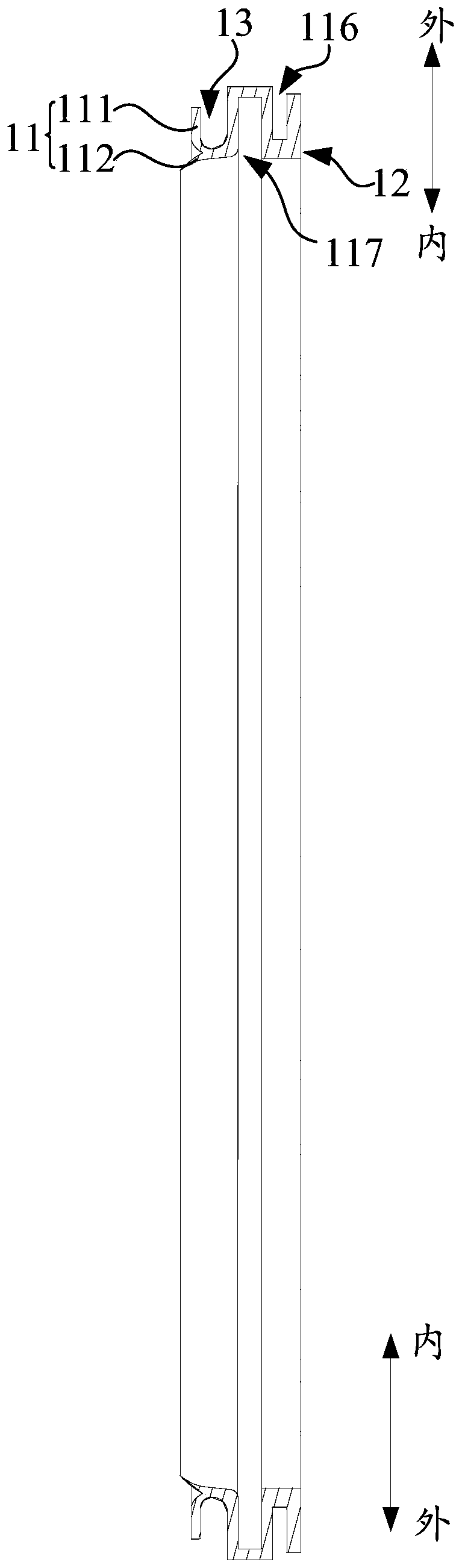
[0051] In addition to the features of the above-mentioned embodiments, it is further defined that: the first lip 121 is connected to the second lip 122 and jointly constructs a bifurcated structure with an opening at one end, the bifurcated structure has two branches, the first lip 121 Part or all of the second lip 122 forms one branch of the bifurcated structure, and part or all of the second lip 122 forms another branch of the bifurcated structure. The first lip 121 is set to be connected with the second lip 122 and jointly construct a bifurcated structure with an opening at one end, so that the opening and closing of the bifurcated structure can be used to further increase the amount of rebound against the sealing part 12, so that when the second When one of the first lip 121 and the second lip 122 abuts against the barrel 30, the one of the first lip 121 and the second lip 122 which abuts against the barrel 30 is deformed and pulled The other rests on the barrel part 30, t...

Embodiment 2

[0054] In addition to the features of any of the above embodiments, it is further defined that the two branches of the bifurcated structure are connected at one end and the other end is a free end, one branch is combined with the connecting end of the other branch, and the free ends are separated from each other , and the distance between one branch and the other branch gradually increases from the connecting end to the free end, so that the opening is formed as a gradually increasing bell mouth. Set the distance between one branch and the other branch to gradually increase from the connecting end to the free end, so that the opening is formed as a gradually increasing bell mouth. The spring ability is stronger, and the structural rebound effect of the abutting sealing part 12 is further improved, thereby further strengthening and improving the abutting sealing effect on the first lip 121 and the second lip 122, improving the sealing reliability, and further improving Opening ...

Embodiment 3

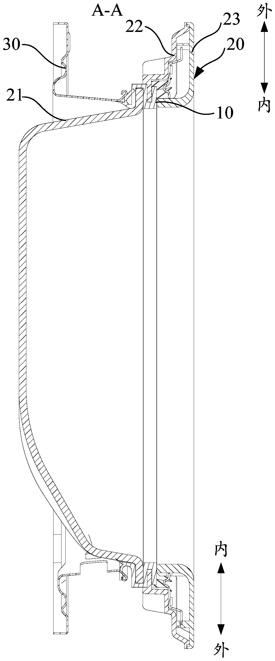
[0057] In addition to the features of any of the above-mentioned embodiments, it is further defined that one of the two branches is located on the outside of the other and protrudes outward obliquely, for example, as Figure 4 As shown, the first lip 121 is located on the outer side of the second lip 122 and is obliquely protruded outward. It can also be understood that the first lip 121 is located on the outer side of the second lip 122 and faces away from the second lip 122. The oblique extension, in this way, is beneficial to increase the contact area between the first lip 121 and the barrel 30 , further strengthening and improving the abutting and sealing effect of the first lip 121 .

[0058] One of the two branches is located on the inner side of the other and protrudes obliquely inwardly. For example, if Figure 4 As shown, the second lip 122 is located on the inner side of the first lip 121 and extends obliquely inward. It can also be understood that the second lip 12...


PUM


Abstract

The invention provides a door seal ring, a door assembly and clothes processing equipment. The door seal ring is provided with a matching body and an abutting seal part which are connected with each other; the abutting seal part comprises a first lip and a second lip connected with each other. According to the technical scheme, the abutting seal part is separated from a tub assembly when a door body is opened, and the abutting seal part is abutted against the tub assembly when the tub assembly is covered with the door body; thus, the sealing between the movable door body and the tub assembly is realized, water leakage of the tub assembly is prevented effectively, and seal reliability and safety of the product are guaranteed; further, since the abutting seal part and the tub assembly are inabutting fit, and the door seal ring keeps in abutting against the tub assembly through its elasticity and can move synchronously with the tub assembly, the leakage between the door body and the tubassembly can be avoided, and the seal reliability of the door body can be improved.

Description

technical field [0001] The invention relates to the field of sealing, in particular to a door sealing ring, a door assembly and a clothes processing device. Background technique [0002] The door glass commonly used in drum washing machines in the market is usually sandwiched between the inner ring of the plastic door and the outer ring of the door. This installation method is usually that the door assembly is installed on the front sealing door. The door assembly only has a closing action and does not follow Moving with the movement of the washing machine, in order to prevent water leakage, it is necessary to install a sealing ring on the barrel of the drum washing machine, but the sealing ring is easy to hide dirt and has poor hygiene. [0003] With the gradual improvement of users' requirements for hygiene and health, drum washing machines have begun to appear without door seals, and washing machines with this structure need a door body to realize the sealing of the barre...

Claims


Application Information

Patent Timeline
IPC IPC(8): D06F39/14D06F23/02
CPCD06F39/14D06F23/02
Inventor 张伟丁浩周震东苗雨来
Owner WUXI LITTLE SWAN ELECTRIC CO LTD
Why Eureka
Try Eureka