Eureka AIR delivers breakthrough ideas for toughest innovation challenges, trusted by R&D personnel around the world.

Manufacturing method of bridge pier

A manufacturing method and bridge pier technology, applied in the manufacture of tools, bridges, bridge parts, etc., can solve problems such as long construction time, difficult concrete pouring, and large traffic volume, so as to improve construction speed and safety, and the connection structure is firm and reliable , The effect of simple construction process

Active Publication Date: 2020-01-07
BYD CO LTD
View PDF9 Cites 7 Cited by
  • Summary
  • Abstract
  • Description
  • Claims
  • Application Information

AI Technical Summary

Problems solved by technology

[0002] In some related technologies, the bridge pier structure usually adopts cast-in-place construction, and it is necessary to set up beam supports, formwork and binding steel bars on the construction site, which requires a large amount of labor, long construction time, and concrete pouring is difficult, dangerous, and low in efficiency. In addition, the noise is large, which has a great impact on the surrounding environment and road traffic
[0003] In other related technologies, the installation of the bridge pier structure is realized by assembling solid prefabricated components. The weight of the solid prefabricated components is large, and the transportation and installation require high equipment, which increases the cost of the measures, and the construction area occupied during installation is large. Affected road traffic, with a large amount of traffic relief

Method used


Image

  • Manufacturing method of bridge pier
  • Manufacturing method of bridge pier
  • Manufacturing method of bridge pier

Examples


Embodiment Construction

[0051] Embodiments of the present invention are described in detail below, examples of which are shown in the drawings, wherein the same or similar reference numerals designate the same or similar elements or elements having the same or similar functions throughout. The embodiments described below by referring to the figures are exemplary only for explaining the present invention and should not be construed as limiting the present invention.

[0052] In describing the present invention, it should be understood that the terms "center", "longitudinal", "transverse", "length", "width", "thickness", "upper", "lower", "front", " Rear", "Left", "Right", "Vertical", "Horizontal", "Top", "Bottom", "Inner", "Outer", "Axial", "Radial", "Circumferential" The orientation or positional relationship indicated by etc. is based on the orientation or positional relationship shown in the drawings, and is only for the convenience of describing the present invention and simplifying the descriptio...


PUM

PropertyMeasurementUnit
heightaaaaaaaaaa

Abstract

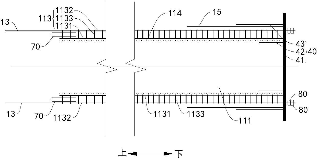
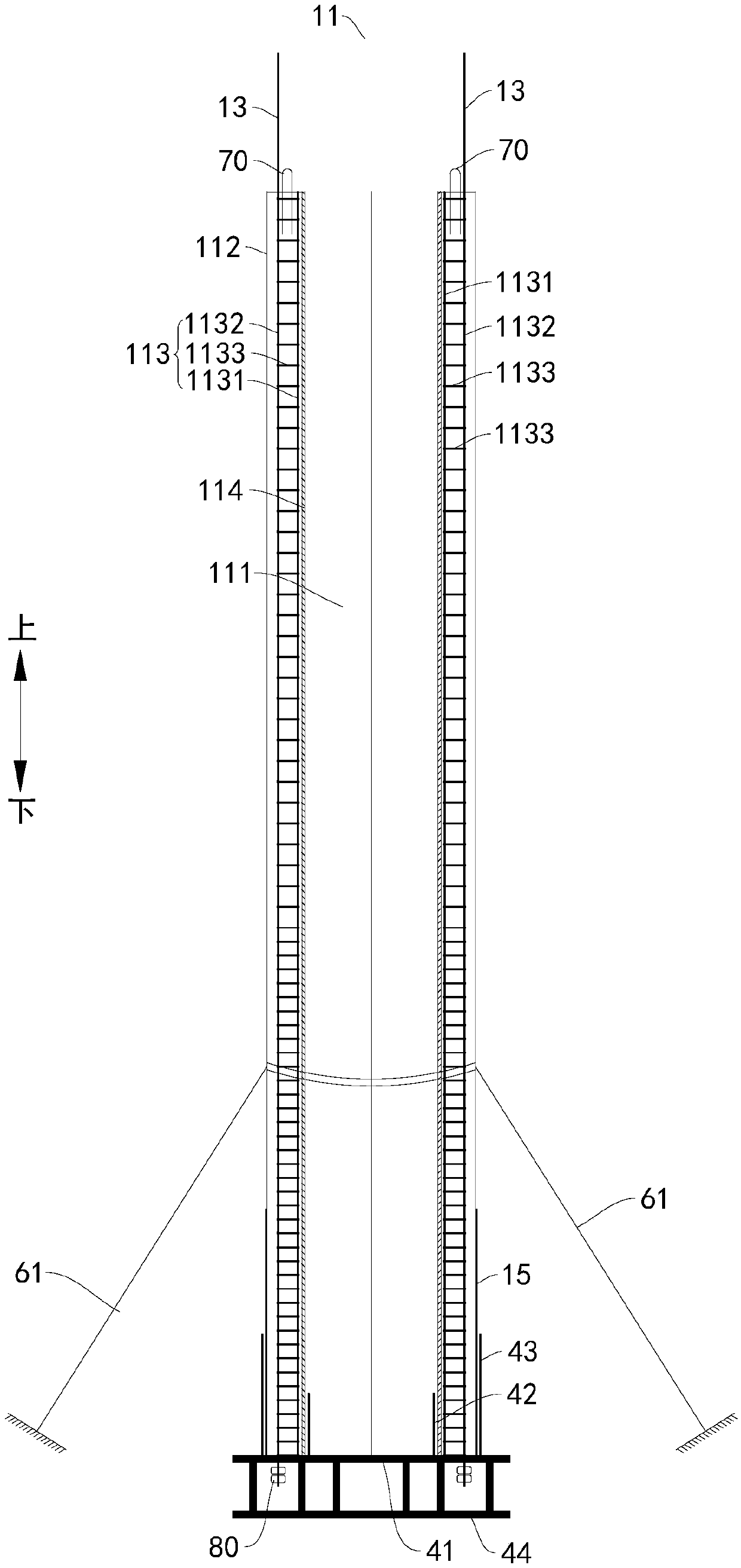
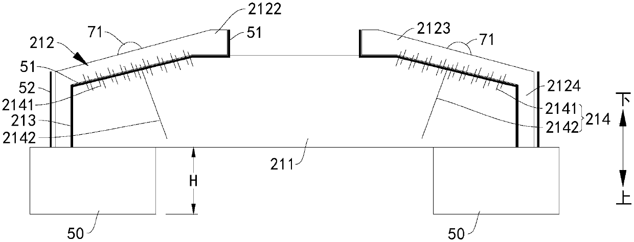
The invention discloses a manufacturing method of a bridge pier. The manufacturing method of the bridge pier comprises the following steps of obtaining a pier stud prefabricated part and a capping beam prefabricated part, wherein a pier stud prefabrication chamber extending in the axial direction is formed in the pier stud prefabricated part; a capping beam prefabrication chamber is formed in thepier stud prefabricated part; a connecting rib extending upwards is arranged on the pier stud prefabricated part; the pier stud prefabricated part is placed on a mounting surface; concrete is injectedinto the pier stud prefabrication chamber from an opening in the upper end of the pier stud prefabrication chamber to be cured to form a pier stud concrete layer; the capping beam prefabricated partis mounted at the upper part of the pier stud prefabricated part, and the connecting rib is enabled to extend into the capping beam prefabrication chamber; and concrete is injected into the capping beam prefabrication chamber to be cured to form a capping beam concrete layer connected with the pier stud concrete layer and the connecting rib. According to the manufacturing method of the bridge pierdisclosed by the embodiment of the invention, the site construction procedure is simple, the construction speed is increased, the construction safety is enhanced, adverse effect of a traditional fullcast-in-situ process on traffic environment is avoided, and moreover, the connection between a pier stud and a capping beam is firmer.

Description

technical field [0001] The present invention relates to the technical field of bridge piers, and more specifically, to a manufacturing method of bridge piers. Background technique [0002] In some related technologies, the bridge pier structure usually adopts cast-in-place construction, and it is necessary to set up beam supports, formwork and binding steel bars on the construction site, which requires a large amount of labor, long construction time, and concrete pouring is difficult, dangerous, and low in efficiency. In addition, the noise is large, which has a great impact on the surrounding environment and road traffic. [0003] In other related technologies, the installation of the bridge pier structure is realized by assembling solid prefabricated components. The weight of the solid prefabricated components is large, and the transportation and installation require high equipment, which increases the cost of the measures, and the construction area occupied during install...

Claims


Application Information

Patent Timeline
Patent Type & Authority Applications(China)
IPC IPC(8): E01D19/02E01D21/00B28B23/02E01D101/28
CPCE01D19/02E01D21/00B28B23/02E01D2101/28
Inventor 杜平张广海张文娜黎婉婉白鸽
Owner BYD CO LTD
Why Eureka
Eureka Blog
Learn More