
Motor-driven vehicle brake power driving device

A motor-driven and power-driven technology, which is applied in the direction of brake actuators, mechanical equipment, gear transmission mechanisms, etc., can solve problems such as single function and simple structure, and achieve optimized bracket structure, easy control, and reduced structural and process costs. Effect

Inactive Publication Date: 2020-01-07
上海茵索汽车科技有限公司
View PDF0 Cites 1 Cited by
  • Summary
  • Abstract
  • Description
  • Claims
  • Application Information

AI Technical Summary

Problems solved by technology

However, the electronic handbrake in the prior art can only realize the parking function driven by the motor, and its self-locking function is realized through the self-locking of the screw thread or the worm gear, and its function is relatively single, and its structure is relatively simple

Method used


Image

  • Motor-driven vehicle brake power driving device
  • Motor-driven vehicle brake power driving device
  • Motor-driven vehicle brake power driving device

Examples


Embodiment Construction

[0041] The present invention will be further described in detail with reference to the following specific embodiments and accompanying drawings. Except for the content specifically mentioned below, the process, conditions, experimental methods, etc. for implementing the present invention are all common knowledge and common knowledge in the field, and the present invention is not particularly limited.

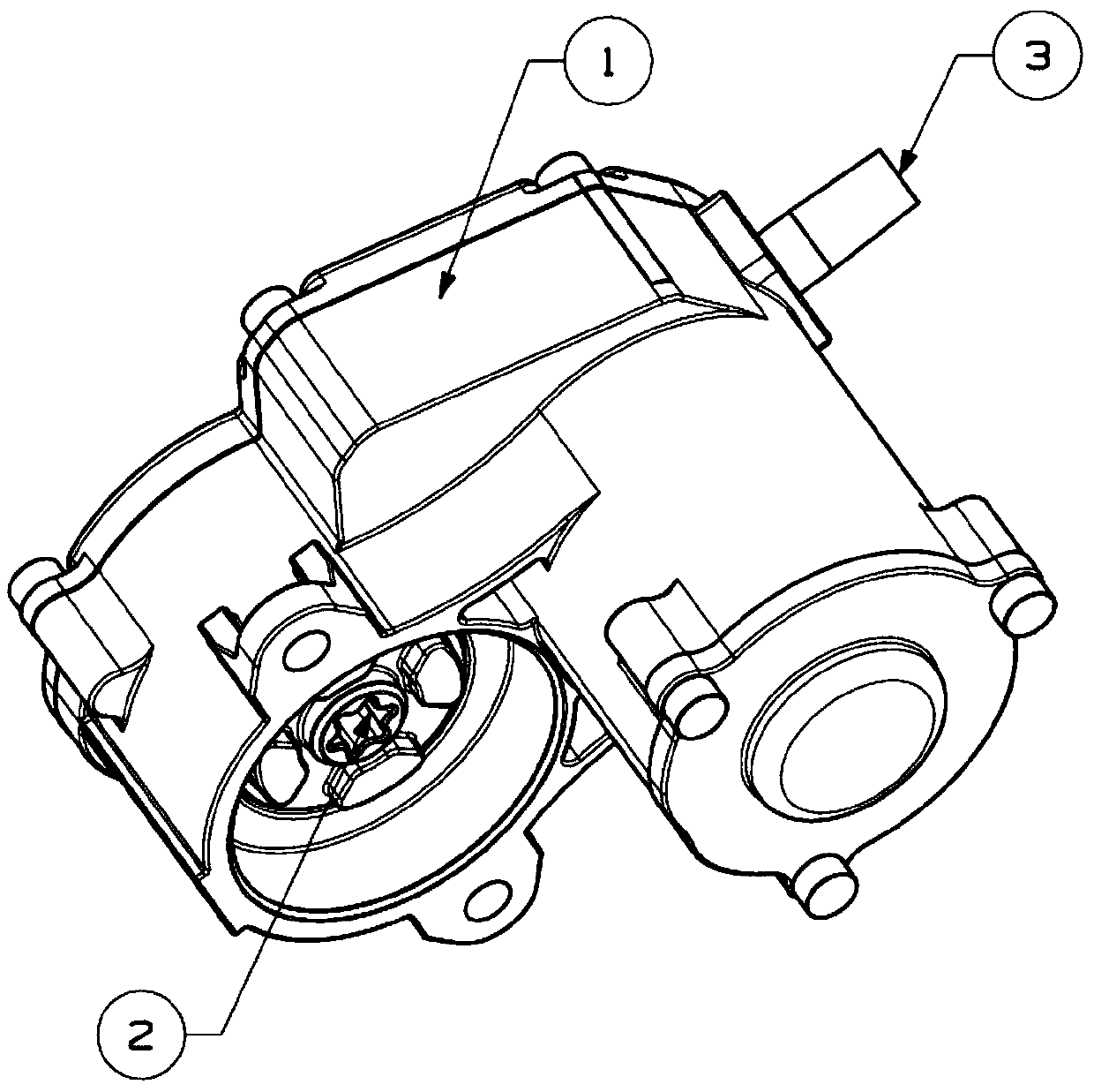
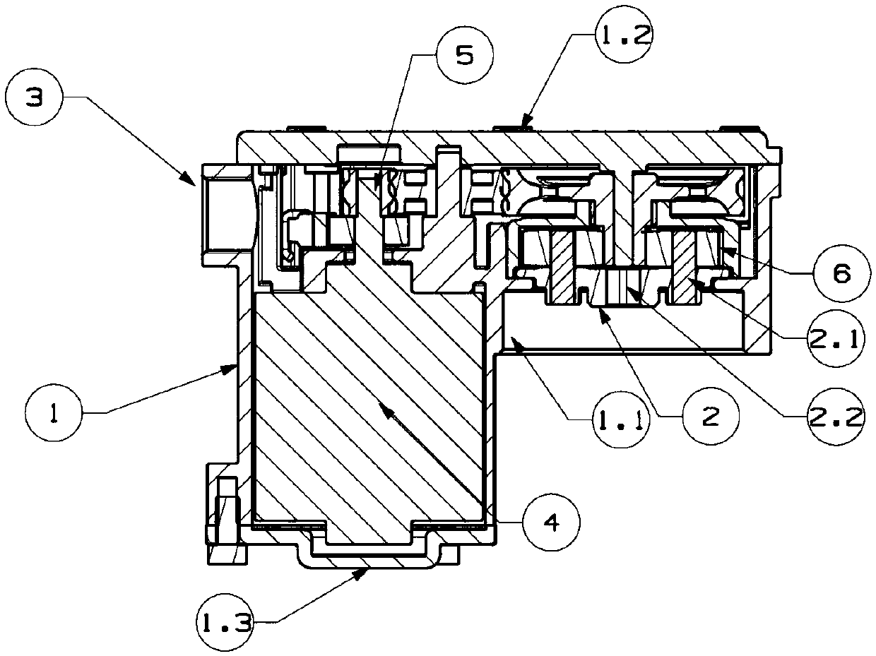
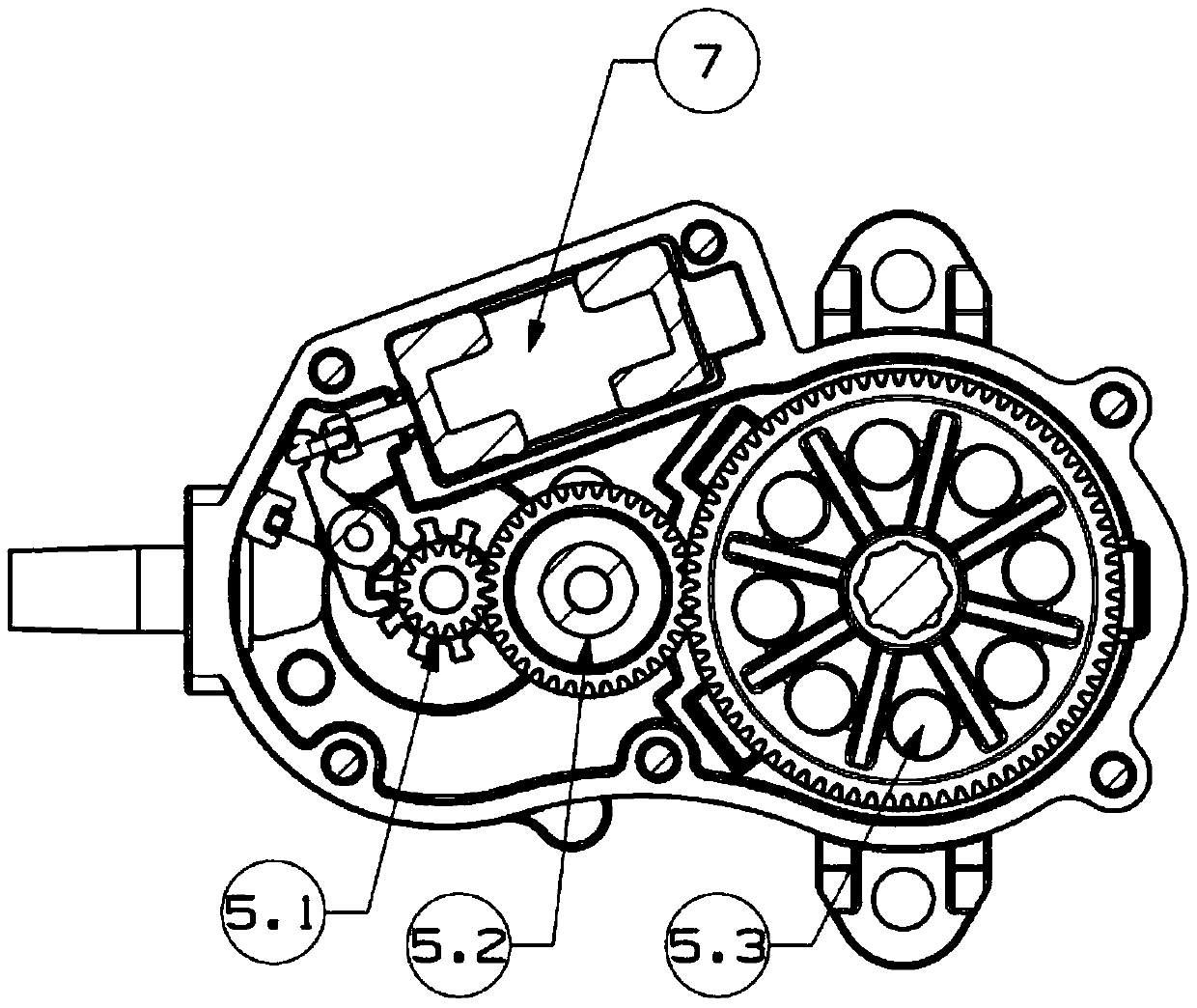
[0042] The motor-driven vehicle brake of the present invention includes a housing 1 , a motor 4 , a transmission mechanism driven by the motor 4 and a self-locking mechanism 7 .

[0043] Housing 1, gearbox end cover and motor end cover, motor 4 and the corresponding transmission mechanism are installed in the housing 1, in which the brushless motor and the housing motor mounting hole 1.1.1 interference fit installation, in order to improve the positioning accuracy and installation accuracy of the motor , the housing 1 is designed to open up and down, wherein the motor 4 is insta...


PUM


Abstract

The invention provides a motor-driven vehicle brake power driving device. The motor-driven vehicle brake power driving device comprises a shell, a motor installed in the shell, a transmission mechanism driven by the motor, and a self-locking mechanism installed on brakes and used for realizing driving force required by vehicle running braking and parking braking brakes for realizing correspondingactions. According to the motor-driven vehicle brake power driving device, different from a traditional hydraulic drive brake, the power driving mechanism is driven through the motor, moreover, the torque required by the brakes is output, and the vehicle running braking and parking braking functions are realize; and the structure of the brake power driving mechanism is optimized, so that the structure cost and the process cost are reduced, and the motor-driven vehicle brake power driving device has a wide application prospect.

Description

technical field [0001] The invention relates to the technical field of vehicle braking, in particular to a motor-driven brake power drive device for vehicles. Background technique [0002] In the prior art, a floating caliper applied to a vehicle disc brake has a main structure including: a caliper body, a bracket, a piston, a friction plate, a guide pin, and other mechanisms that provide sliding support and sealing. as attached Figure 7 As shown, the mechanism is a traditional hydraulic brake mechanism, which uses brake fluid to push the piston forward and press the friction plate to achieve vehicle braking; the conventional parking brake uses a set of additional brakes installed on the caliper. The mechanical mechanism is realized. In addition to the above-mentioned floating calipers, the hydraulic braking system also needs to be equipped with a complete set of hydraulic reserve and pressure building devices: such as liquid storage tanks, boosters, etc.; pressure buildin...

Claims


Application Information

Patent Timeline
IPC IPC(8): F16D65/14F16D121/14F16D121/24F16D125/50
CPCF16D65/14F16D2121/14F16D2121/24F16D2125/50
Inventor 不公告发明人
Owner 上海茵索汽车科技有限公司
Learn More