Self-lubricating gear

A self-lubricating, gear technology, applied in the direction of engine lubrication, gear lubrication/cooling, belt/chain/gear, etc., to achieve the effect of easy production, simple structure, good lubrication and heat dissipation

Pending Publication Date: 2020-01-07
宁波思洞工业设计有限公司
View PDF6 Cites 2 Cited by
  • Summary
  • Abstract
  • Description
  • Claims
  • Application Information

AI Technical Summary

Problems solved by technology

But it also brings special problems that must be solved in the design

Method used


Image

  • Self-lubricating gear
  • Self-lubricating gear
  • Self-lubricating gear

Examples


Embodiment Construction

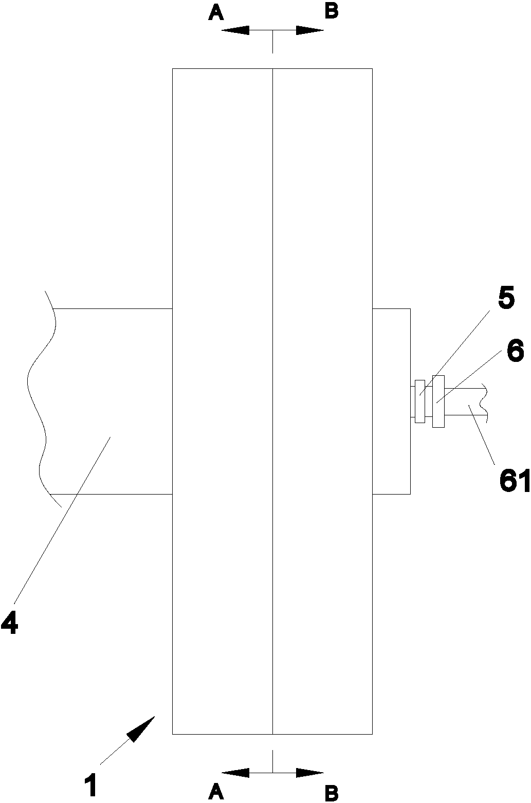
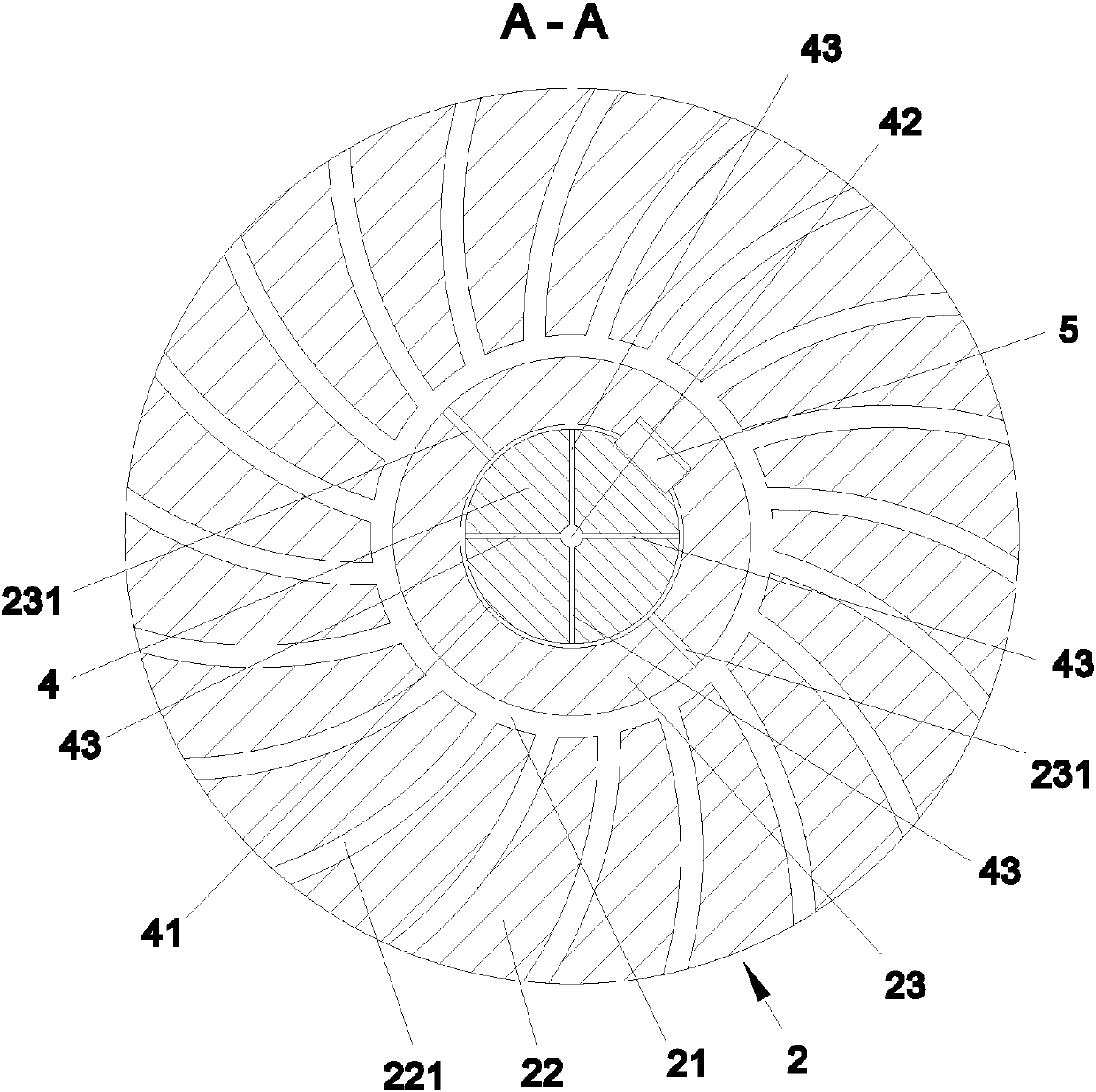
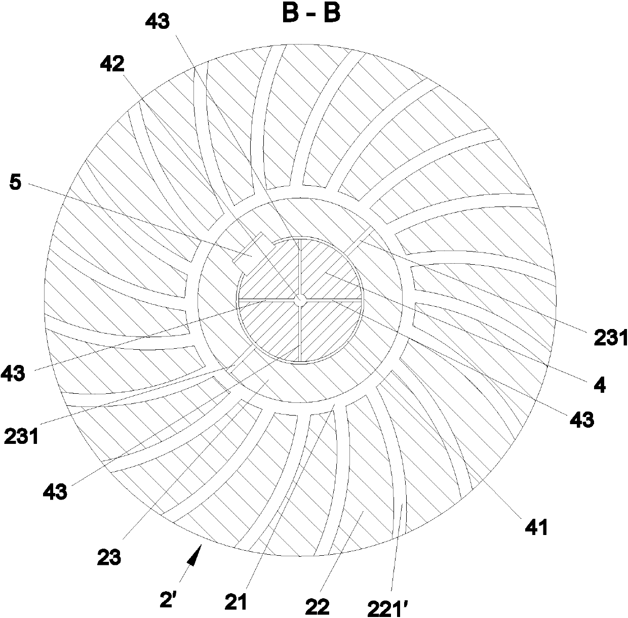
[0019] The present invention will be described in further detail below in conjunction with accompanying drawing and specific embodiment: figure 1 to attach image 3 As shown, a self-lubricating gear includes a gear part 1, and a rolling shaft 4 is arranged in the center of the gear part 1. The gear part 1 is composed of two toothed discs with the same material. The toothed discs shown It is divided into a toothed disc 2 and a second toothed disc 2'. The circular end surface of the first toothed disc 2 is provided with an inner ring groove 21, and the inner ring groove 21 is connected with several arc-shaped guide grooves radiating to the outer circular surface. 221, the outlet of the arc guide groove 221 is located at the root of the tooth, the inner ring groove 21 is connected with an outer oil pipe 231, and the outer oil pipe 231 is symmetrically arranged and leads to the inner circular surface; the rolling shaft 4. The outer circular surface is provided with an outer ring ...


PUM


Abstract

The invention discloses a self-lubricating gear. The self-lubricating gear comprises a gear part; a rolling shaft is arranged at the middle part of the gear part; the gear part is formed by bonding two tooth discs made of identical materials; the tooth discs are divided into a first tooth disc and a second tooth disc; an inner ring groove is formed in the circular end surface of the first tooth disc; the inner ring groove is connected with a plurality of arc-shaped guide grooves radiating towards the external circle surface; the inner ring groove is connected with outer communicating oil pipes; the outer communicating oil pipes are symmetrically arranged and lead to the internal circle surface; an outer ring groove is formed in the external circle surface of the rolling shaft; the outer communicating oil pipes communicate with the inner ring groove and the outer ring groove; an oil conveying pipe is arranged at the middle part of the rolling shaft; four inner communicating oil pipes distributed in an equally-divided manner are connected between the oil conveying pipe and the outer ring groove; the structure of the second tooth disc is consistent with that of the first tooth disc; the bending directions of arc-shaped guide grooves in the second tooth disc are opposite to those of the arc-shaped guide grooves in the first tooth disc; and the positions of outlets of the arc-shapedguide grooves in the second tooth disc and the positions of outlets of the arc-shaped guide grooves in the first tooth disc are overlapped. The self-lubricating gear has the self-lubricating effect,lubricating oil can be spilt out automatically in the working process of the gear, and the self-lubricating gear has the good lubricating and heat-dissipation function.

Description

technical field [0001] The invention relates to a self-lubricating gear. Background technique [0002] A gear is a mechanical element with gears on the rim that continuously mesh to transmit motion and power. The application of gears in transmission has appeared very early. At the end of the 19th century, the principle of generative gear cutting method and special machine tools and cutting tools using this principle appeared one after another. With the development of production, the stability of gear operation was paid more attention. [0003] Harmonic gear transmission is a new type of mechanism that relies on elastic deformation motion to achieve transmission. It breaks through the mode of mechanical transmission using rigid components, and uses a flexible component to achieve mechanical transmission, thus obtaining a series of other transmissions that are difficult to achieve. Its special features have been widely used. But it also brings special problems that must be ...

Claims


Application Information

Patent Timeline
Patent Type & Authority Applications(China)
IPC IPC(8): F16H55/17F16H57/04F16N1/00
CPCF16H55/17F16H57/043F16N1/00
Inventor 张开发
Owner 宁波思洞工业设计有限公司
Why Eureka
Try Eureka