Microwave resonant cavity and electron paramagnetic resonance probe using same

An electron paramagnetic resonance and microwave resonant cavity technology, applied in the field of microwave resonant cavity and electron paramagnetic resonance probe, can solve the problems of poor coupling ability of low-frequency modulation field, low Q value, single coupling structure and function, etc., and achieve strong coupling ability. , the effect of improving the conversion efficiency

Pending Publication Date: 2020-01-07
CHINAINSTRU & QUANTUMTECH (HEFEI) CO LTD
View PDF0 Cites 4 Cited by
  • Summary
  • Abstract
  • Description
  • Claims
  • Application Information

AI Technical Summary

Problems solved by technology

The existing resonant cavity has the following problems: (1) the filling factor is low, and the level of the filling factor determines the height of the magnetic field conversion efficiency. Although the rectangular cavity and the cylindrical cavity have high Q values, in some extremely low-sensitivity samples, Still unable to detect the EPR signal; (2) The quality factor is low, and the Q value is one of the important factors determining the strength of the EPR signal. This type of resonant cavity is used; (3) the coupling structure has a single function. The existing resonant cavity focuses on critical coupling, and often ignores the use of the resonant cavity in the over-coupled state. In some special applications, such as pulsed electron paramagnetic resonance spectrometer, it is The low-Q resonant cavity under the condition of over-coupling can be used; (4) the coupling ability of the low-frequency modulation field is poor, and the phase-sensitive detection technology used in the electron paramagnetic resonance spectrometer needs to couple a certain intensity of the modulated magnetic field into the resonant cavity , the coupling ability of the existing coupling structure is poor

Method used


Image

  • Microwave resonant cavity and electron paramagnetic resonance probe using same
  • Microwave resonant cavity and electron paramagnetic resonance probe using same
  • Microwave resonant cavity and electron paramagnetic resonance probe using same

Examples


Embodiment 1

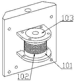
[0026] A microwave resonator 1 with low-frequency modulation field coupling capability, such as figure 1 shown, including vertically arranged ring-shaped sapphire crystals ( figure 1 not shown) and a metal sleeve 101 sleeved on the outside of the ring-shaped sapphire crystal, and a plurality of slits 102 are provided on the metal sleeve at equal intervals horizontally. The ring-shaped sapphire crystal preferably has an outer diameter of 10 mm, an inner diameter of 5 mm, and a height of 13 mm; preferably 10 gaps, each with a height of 0.18 mm, and the distance between two adjacent gaps is 1 mm.

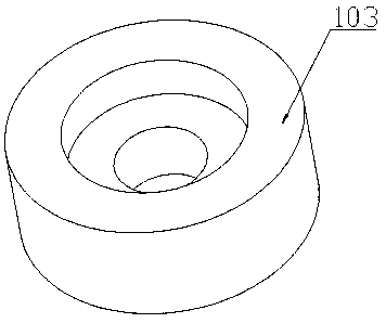
[0027] The upper and lower sides of the ring-shaped sapphire crystal are limited and fixed by the Teflon gasket 103 with internal steps to ensure that the ring-shaped sapphire crystal is stably arranged inside the metal sleeve, and the size of the steps matches the size of the ring-shaped sapphire crystal. Teflon gasket structure such as figure 2 shown. Teflon has a small dielectri...

Embodiment 2

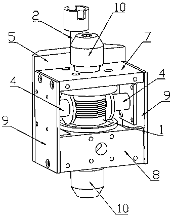
[0030] An electron paramagnetic resonance probe, such as Figure 3-5 As shown, it includes the microwave resonant cavity 1 described in Embodiment 1, a tuning unit fixedly connected to the microwave resonant cavity, and a coupling unit between the tuning unit and the microwave resonant cavity. The side is provided with a Helmertz coil 4, and the Helmertz coil 4 is composed of a horizontally fixed coil fixing mechanism and an enameled wire coil wound thereon, and the coil fixing mechanism is made of an insulating material; the microwave resonator 1 and the Helmhertz coil 4 are enclosed in the housing.

[0031] Specifically, in this embodiment, the size of the annular sapphire crystal is 10mm in outer diameter, 5mm in inner diameter, and 13mm in height; the size of the metal sleeve is 18mm in outer diameter, 16mm in inner diameter, and 16mm in height; the enameled wire coil is preferably made of enameled wire with a diameter of 0.51mm It is made by winding 110 turns on the coil...


PUM

PropertyMeasurementUnit
heightaaaaaaaaaa
heightaaaaaaaaaa
Resonant frequencyaaaaaaaaaa

Abstract

The invention discloses a microwave resonant cavity and an electron paramagnetic resonance probe using the same. The microwave resonant cavity comprises a vertically arranged annular sapphire crystaland a metal sleeve which sleeves the annular sapphire crystal, and the metal sleeve is horizontally and annularly provided with a plurality of gaps at equal interval. The electron paramagnetic resonance probe comprises the microwave resonant cavity, a tuning unit fixedly connected with the microwave resonant cavity, and a coupling unit positioned between the tuning unit and the microwave resonantcavity, Helmholtz coils are arranged on the two sides of the microwave resonant cavity respectively, each Helmholtz coil is composed of a horizontally-fixed coil fixing mechanism and an enameled wirecoil wound on the coil fixing mechanism, and the coil fixing mechanisms are made of insulating materials; and the microwave resonant cavity and the Helmholtz coils are sealed in a shell. A special modulation field coupling structure is used, the modulation field coupling capacity is high, and the modulation field conversion efficiency is greatly improved.

Description

technical field [0001] The invention relates to the technical field of electron paramagnetic resonance, in particular to a microwave resonant cavity with low-frequency modulation magnetic field coupling function and an electron paramagnetic resonance probe using the same. Background technique [0002] Electron paramagnetic resonance (electron paramagnetic resonance, EPR) is a magnetic resonance technique originating from the magnetic moment of unpaired electrons. Structural properties of the surrounding environment. [0003] In electron paramagnetic resonance experiments, resonant cavities play an important role. To meet different experimental requirements, resonant cavities also have different forms, commonly used are rectangular cavities, cylindrical cavities, dielectric cavities, and cracked cavities. The existing resonant cavity has the following problems: (1) the filling factor is low, and the level of the filling factor determines the height of the magnetic field con...

Claims


Application Information

Patent Timeline
Patent Type & Authority Applications(China)
IPC IPC(8): G01N24/10
CPCG01N24/10
Inventor 苏陶石致富
Owner CHINAINSTRU & QUANTUMTECH (HEFEI) CO LTD
Why Eureka
Try Eureka