Non-contact disassembly detection mutual inductor

A non-contact, transformer technology, applied in the field of transformers, can solve problems such as hidden safety hazards, current transformer damage, equipment damage, etc., and achieve the effect of increasing opening loosening or opening detection, quick disconnection detection, and sensitive magnetic induction.

Pending Publication Date: 2020-01-07
锱云(上海)物联网科技有限公司
View PDF0 Cites 0 Cited by
  • Summary
  • Abstract
  • Description
  • Claims
  • Application Information

AI Technical Summary

Problems solved by technology

[0003] The function of the transformer is single. The current transformer on the market only has a simple current collection function, and cannot detect the disconnection or loosening of the buckle of the current transformer. As a result, it is impossible to know in time when the current transformer is damaged or faulty, resulting in installation failures. The equipment is damaged and there are potential safety hazards

Method used


Image

  • Non-contact disassembly detection mutual inductor
  • Non-contact disassembly detection mutual inductor
  • Non-contact disassembly detection mutual inductor

Examples


Embodiment 1

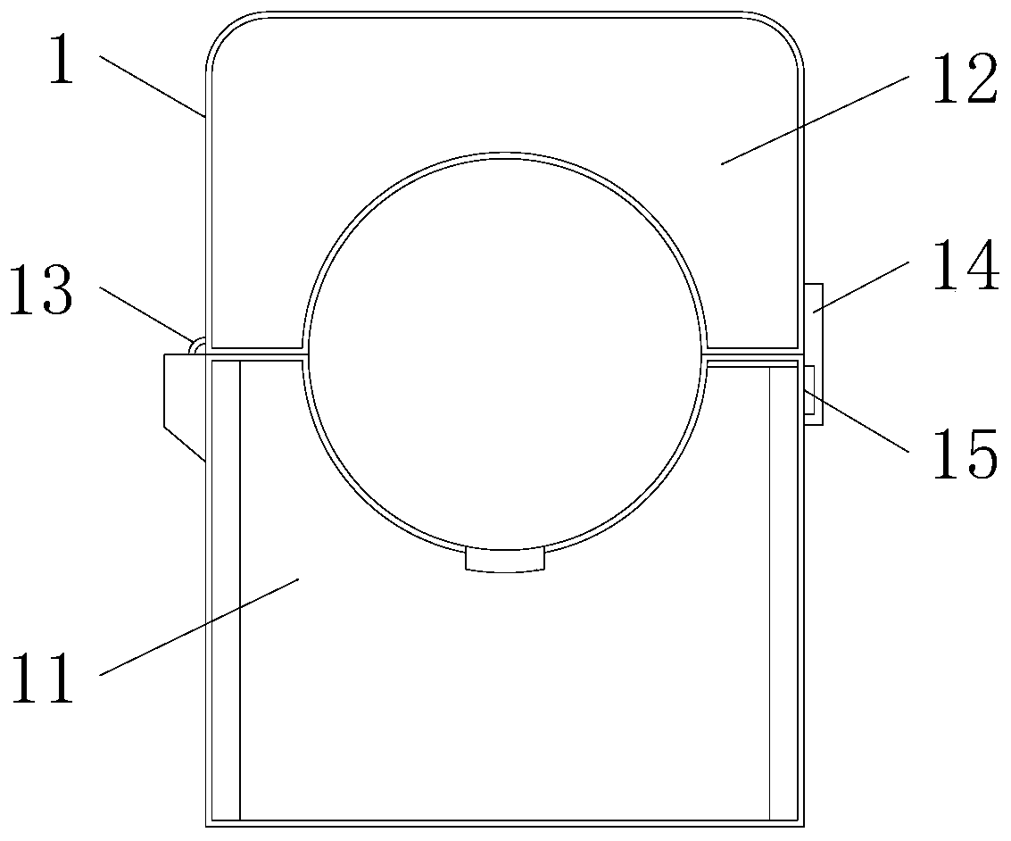
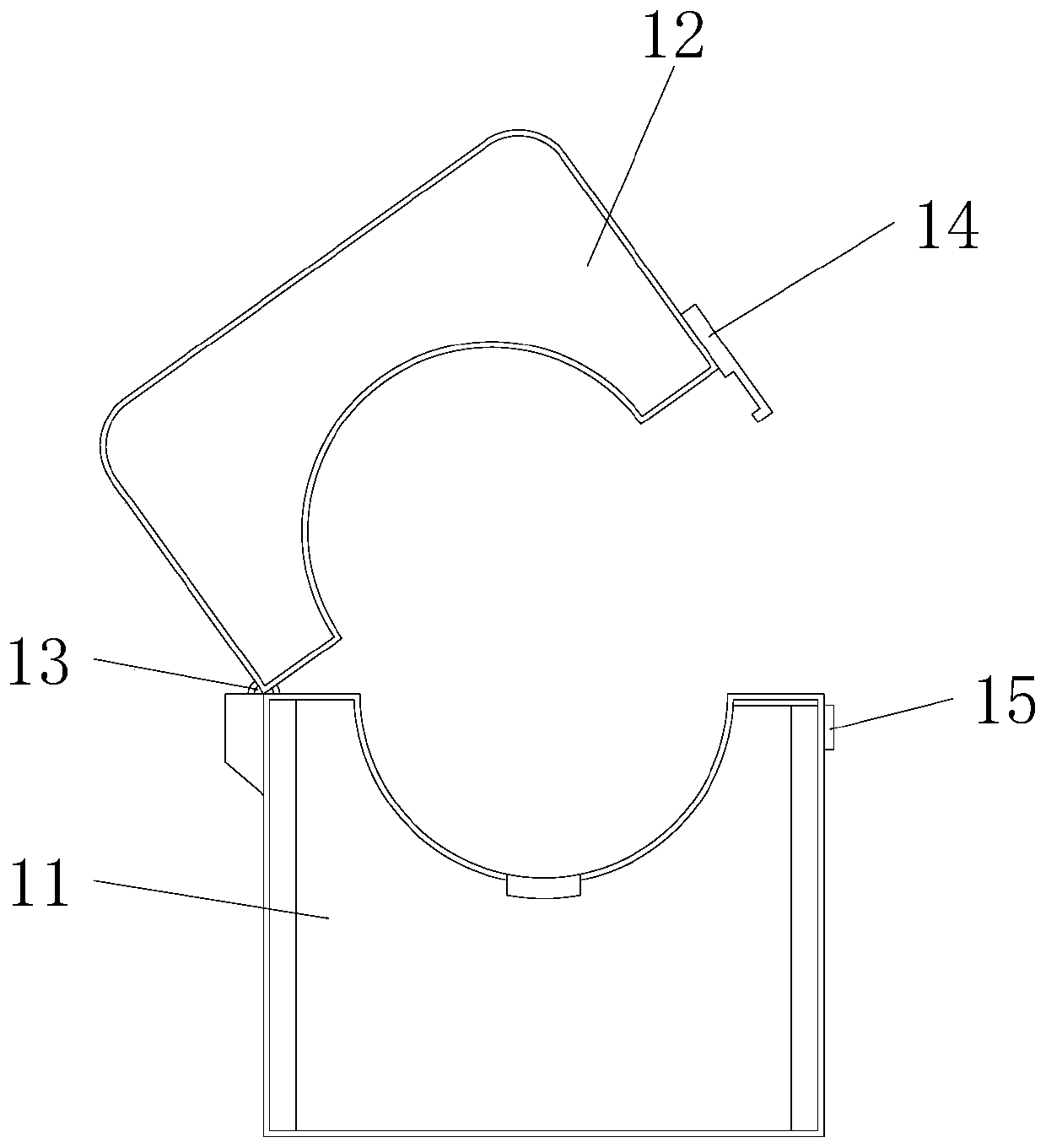
[0024] see Figure 1-2 The present invention provides a non-contact disassembly detection transformer. The transformer 1 includes a cable holder 12 and a cable base 11 arranged up and down. One end of the connection between the cable base 11 and the cable holder 12 is provided with a Hinge 13, the cable base 11 and the cable holder 12 are rotatably connected by the hinge 13, and the end of the conflict between the cable base 11 and the cable holder 12 is symmetrically provided with an arc-shaped cable groove , the cable holder 12 is fixed with a raised buckle 14, the cable base 11 is fixed with a raised buckle locator 15, and the buckle 14 is provided with a groove matching the buckle locator 15, The cable holder 12 and the hinge 13 are fixedly connected by a buckle 14 and a buckle positioning member 15 .

[0025] As an example of the opening and closing of the transformer: the hinge 13 on the top of the cable base 11 is turned over, and the hinge between the cable holder 12 ...

Embodiment 2

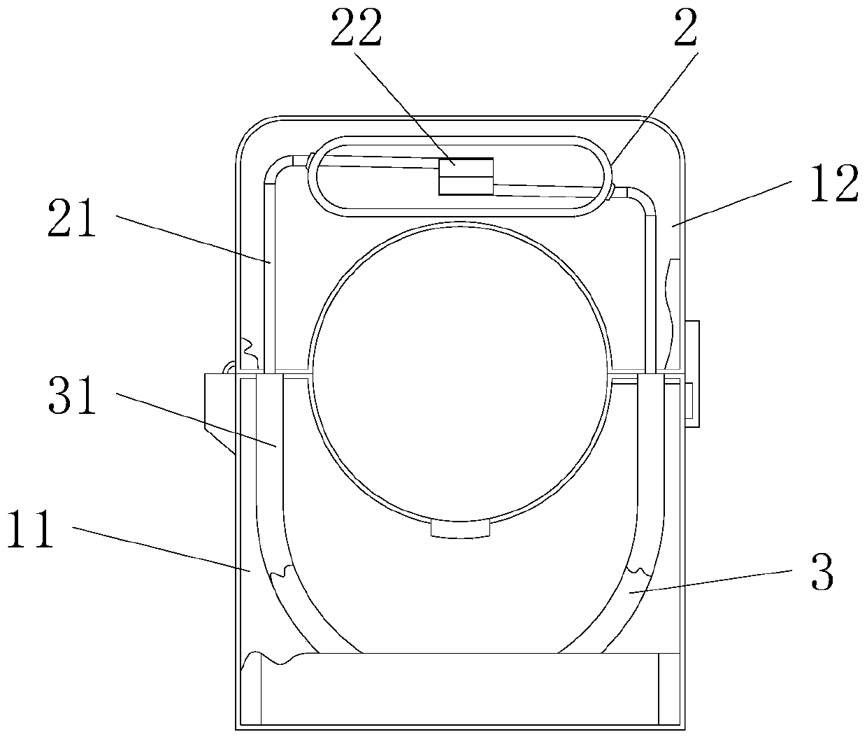
[0027] see Figure 3-4 , the present invention provides a non-contact disassembly detection transformer, a magnet 3 is installed inside the cable base 11, and the two magnetic poles 31 on the magnet 3 both penetrate the upper surface of the cable base 11, symmetrically , a reed switch 2 is installed inside the cable holder 12, and two reeds 21 are arranged inside the reed switch 2, and the close ends of the two reeds 21 are symmetrically connected to a contact part 22, and the reed switch 2 The two reeds 21 both pass through the lower surface of the cable holder 12 .

[0028] It should be noted:

[0029] 1. When the cable base 11 and the cable holder 12 are closed, the end surface of the magnetic terminal post 31 penetrating the cable base 11 and the end surface of the reed 21 penetrating the cable holder 12 are adsorbed, and the reed 21 and the magnetic terminal post 31 During suction, the two contact parts 22 on the two reeds 21 are closed.

[0030] 2. When the cable base...


PUM


Abstract

The invention belongs to the technical field of mutual inductors, and particularly relates to a non-contact disassembly detection mutual inductor. The non-contact disassembly detection mutual inductorcomprises a mutual inductor, wherein the mutual inductor comprises a cable clamping seat and a cable base which are arranged up and down, a hinge is arranged at one end of the junction of the cable base and the cable clamping seat, the cable base and the cable clamping seat are rotationally connected through the hinge, cable clamping grooves with arc structures are symmetrically formed in one end, which is abutted against the cable clamping seat, of the cable base, the cable base is internally provided with a magnet piece, two magnetic pole end columns on the magnet piece penetrate through the upper surface of the cable base, a reed switch is symmetrically arranged inside the cable clamping seat, two reeds are arranged inside the reed switch, and the ends, which are close to each other, of the two reeds are symmetrically connected with contact parts. According to the invention, the external structure of the mutual inductor is not changed, a non-contact and magnetic induction mode is adopted, and the looseness or opening detection of the opening is increased.

Description

technical field [0001] The invention belongs to the technical field of transformers, in particular to a non-contact disassembly detection transformer. Background technique [0002] Open-type current transformers are mainly used in power distribution system renovation projects. They are easy to install, do not need to dismantle the busbar once, and can also be operated live without affecting the normal power consumption of customers. It saves manpower, material resources, and financial resources for user renovation projects and improves efficiency. This series of current transformers can be used in conjunction with relay protection, measurement and metering devices. [0003] The function of the transformer is single. The current transformer on the market only has a simple current collection function, and cannot detect the disconnection or loosening of the buckle of the current transformer. As a result, it is impossible to know in time when the current transformer is damaged o...

Claims


Application Information

Patent Timeline
Patent Type & Authority Applications(China)
IPC IPC(8): H01F27/40H01F38/30
CPCH01F27/40H01F27/402H01F38/30
Inventor 李纲
Owner 锱云(上海)物联网科技有限公司
Why Eureka
Try Eureka